Contents
Engineering Data & Specifications
Marley MC Fluid Cooler
Specifications / Options
Marley / MC Fluid Cooler / Table of Contents
Specifications / Base
Convenience and Safety Options
Water Distribution System
Marley / MC Fluid Cooler
Air Movement Package
Structure
The Marley MC Fluid Cooler is particularly suited to the urban environment, reducing noise while increasing energy efficiency and performance. By keeping the process fluid in a clean, closed loop, and combining the function of a cooling tower and heat exchanger into one system, they provide superior operational and maintenance benefits
Marley / MC Fluid Cooler
SIDE ELEVATION
Weight
Dimensions
Shipping Weight kg
Motor
Page
Weight
Dimensions
Shipping Weight kg
Motor
Page
Weight
Dimensions
Shipping Weight kg
Motor
VIEW A
SUPPORTING STEEL
Model
80MAX
E D C
AIR INLET ELEVATION
Electric Basin Heaters
Fluid Cooler Coil
Fluid Cooling Recirculating Water
Indoor Storage Tank
Blowdown
Water Treatment
Specification Value
Marley / MC Fluid Cooler / Specifications Base
Specifications
3.0Performance Warranty
Specification Value
Marley / MC Fluid Cooler / Specifications Base
Specifications
4.0Coil
Specification Value
Marley / MC Fluid Cooler / Specifications Base
Specifications
7.0Mechanical Equipment
Specification Value
Marley / MC Fluid Cooler / Specifications Base
Specifications
Access
Stainless Steel Options
Specifications
Specification Value
Stainless Steel Collection Basin
Convenience and Safety Options
Specifications
Specification Value
Top Access Platform
Access Door Platform
Specifications
Specification Value
Distribution System Access Door Platform
Vibration Limit Switch
Specifications
Specification Value
Basin Heater
Specification Value
Specifications
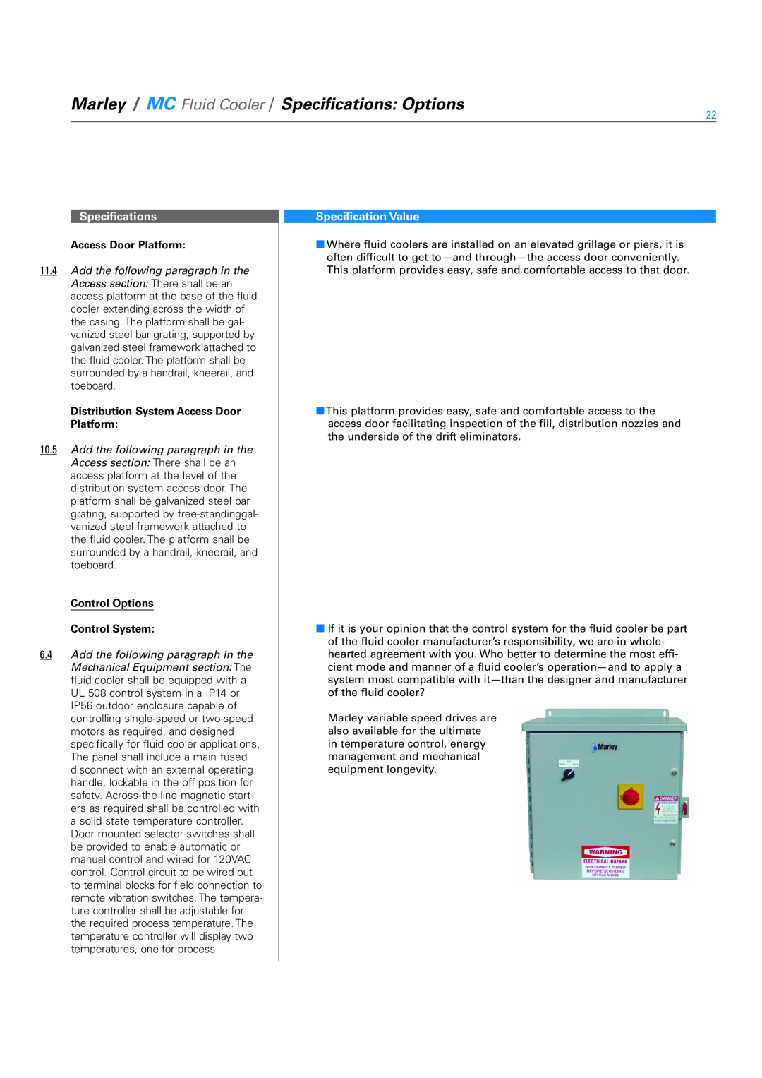
Marley Premium VFD System
Specification Value
Specifications
teeth or drive shafts. The VFD shall catch a fan spinning in the reverse direction without tripping. The panel shall include a main disconnect with short circuit pro- tection and external operating handle, lockable in the off position for safety. The system shall include a solid state, PI temperature controller to adjust fre- quency output of the drive in response to the tower fluid temperature. The temperature of the fluid and set point shall be displayed on the door of the control panel. The bypass shall include a complete magnetic bypass circuit with capability to isolate the VFD when in the bypass mode. Transfer to the bypass mode shall be automatic in the event of VFD failure or for specific trip conditions allowing safe transfer of utility voltage to the motor. Automatic bypass with an earth ground condition is not allowed. The bypass contactor shall be cycled on and off while operating in bypass, to maintain the set-pointtemperature of the fluid. The drive design shall be oper- ated as a stand-alonesystem without the need for a BMS system. Operator controls shall be mounted on the front of the enclosure and shall consist of start and stop control, bypass/VFD selector switch, Auto/Manual selector switch, manual speed control, and solid-statetemperature controller. An emergency bypass selector switch internal to the panel allowing the fluid cooler fan motor to be run at full speed shall be furnished. To prevent heating problems in the fluid cooler fan motor and to assure proper gear box lubrication the VFD system shall de energize the motor once 25% motor speed is reached and cooling is no longer required. The VFD shall include de-icinglogic with auto canceling and adjustable time. Speed in De-Icemode shall not exceed 50% motor speed. The fluid cooler manufacturer shall supply VFD start-upassistance. Tower vibration testing throughout the speed range is required to identify and lockout any natu- ral frequency vibration levels which may exceed CTI guidelines
Specification Value
Specifications
Miscellaneous Options Sound Control
Specification Value
Specifications
Discharge Hood
GREGORYS BANK WORCESTER WR3 8AB UNITED KINGDOM
2008 SPX Cooling Technologies uk MCF-TS-08A