ASSEMBLY INSTRUCTIONS
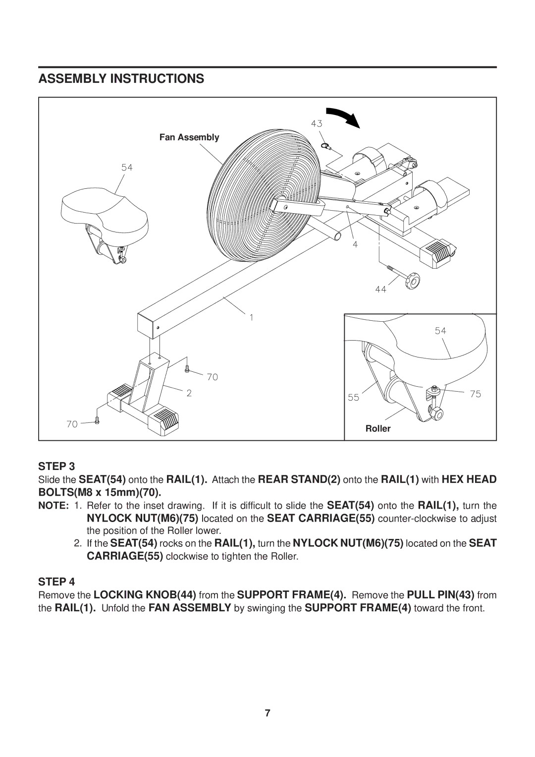
Fan Assembly |
Roller |
STEP 3
Slide the SEAT(54) onto the RAIL(1). Attach the REAR STAND(2) onto the RAIL(1) with HEX HEAD
BOLTS(M8 x 15mm)(70).
NOTE: 1. Refer to the inset drawing. If it is difficult to slide the SEAT(54) onto the RAIL(1), turn the NYLOCK NUT(M6)(75) located on the SEAT CARRIAGE(55)
2.If the SEAT(54) rocks on the RAIL(1), turn the NYLOCK NUT(M6)(75) located on the SEAT CARRIAGE(55) clockwise to tighten the Roller.
STEP 4
Remove the LOCKING KNOB(44) from the SUPPORT FRAME(4). Remove the PULL PIN(43) from the RAIL(1). Unfold the FAN ASSEMBLY by swinging the SUPPORT FRAME(4) toward the front.
7