| Oval | Horizontal |
|
| track |
| |
| bearing |
| |
| Torsion |
| |
|
|
| |
|
| keyed shafts |
|
|
| Center | End |
|
| bearing | |
|
| bearing | |
Center |
| bracket | |
Coupler |
| ||
bearing |
|
| |
half |
|
| |
| Center bracket |
| |
| Center |
| |
| bearing | Oval |
|
|
|
| |
|
| bearing |
|
End |
| Coupler half |
|
|
|
| |
bearing | Oval | Center |
|
bracket |
| ||
| bearing | bracket |
|
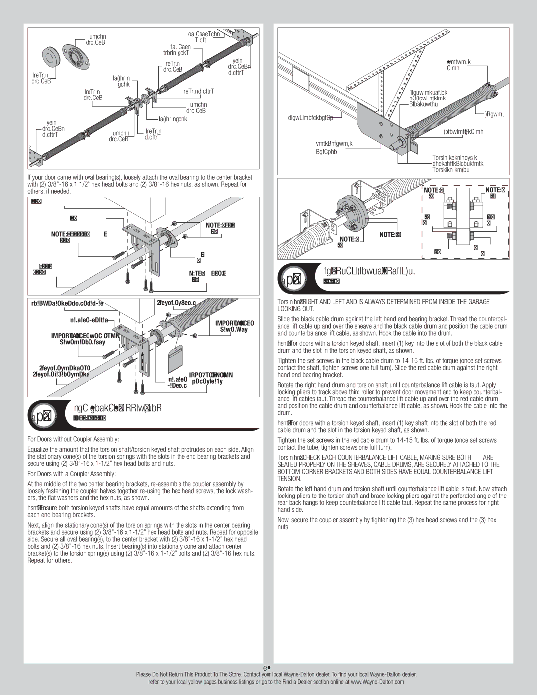
If your door came with oval bearing(s), loosely attach the oval bearing to the center bracket with (2)
Adequate framing member |
|
Center bracket | (2) 3/8” - 16 |
| |
(2) 3/8” - 16 x | Hex nuts |
Hex head nolts |
|
| Oval |
Torsion shaft / | bearing |
| |
Torsion Keyed shaft | (3) 5/16” x 2” |
| Lag screws |
Adequate framing member | Torsion spring | |
Center bracket |
| (2) 3/8” - 16 |
|
| |
(2) 3/8” - 16 x |
| Hex nuts |
|
| |
Hex head nolts |
|
|
Torsion shaft / |
|
|
Torsion Keyed shaft | Center | (3) 5/16” x 2” |
| Lag screws | |
| bearing |
|
20 | Torsion Spring Attachment |
Tools: Ratchet Wrench, 3/8” Socket, 3/8”,9/16” Wrench |
For Doors without Coupler Assembly:
Equalize the amount that the torsion shaft/torsion keyed shaft protrudes on each side. Align the stationary cone(s) of the torsion springs with the slots in the end bearing brackets and secure using (2)
For Doors with a Coupler Assembly:
At the middle of the two center bearing brackets,
NOTE: Ensure both torsion keyed shafts have equal amounts of the shafts extending from each end bearing brackets.
Next, align the stationary cone(s) of the torsion springs with the slots in the center bearing brackets and secure using (2)
| Winding |
| cone |
| Torsion shaft |
| equalized on |
| both sides |
Horizontal track | Spring |
|
Stationary cone
End bearing |
|
|
|
bracket |
| ||
|
| ||
| Hex head bolts and |
| |
| 3/8” - 16 nuts |
|
|
| Coupler |
| Coupler |
| half |
| half |
| (6) Flat |
| (3) Lock |
| washers |
| washers |
Coupler | Coupler halves |
|
|
|
|
| |
assembly | (3) Hex nuts | (3) Hex head | |
|
| screws | |
21 | Counterbalance Lift Cables |
Tools: Locking pliers, 3/8” Wrench |
IMPORTANT: RIGHT AND LEFT AND IS ALWAYS DETERMINED FROM INSIDE THE GARAGE LOOKING OUT.
Slide the black cable drum against the left hand end bearing bracket. Thread the counterbal- ance lift cable up and over the sheave and the black cable drum and position the cable drum and counterbalance lift cable, as shown. Hook the cable into the drum.
NOTE: For doors with a torsion keyed shaft, insert (1) key into the slot of both the black cable drum and the slot in the torsion keyed shaft, as shown.
Tighten the set screws in the black cable drum to
Rotate the right hand drum and torsion shaft until counterbalance lift cable is taut. Apply locking pliers to track above third roller to prevent door movement and to keep counterbal- ance lift cables taut. Thread the counterbalance lift cable up and over the red cable drum and position the cable drum and counterbalance lift cable, as shown. Hook the cable into the drum.
NOTE: For doors with a torsion keyed shaft, insert (1) key shaft into the slot of both the red cable drum and the slot in the torsion keyed shaft, as shown.
Tighten the set screws in the red cable drum to
IMPORTANT: Check each counterbalance lift cable, making sure both are seated properly on the sheaves, cable drums, are securely attached to the bottom corner brackets and both sides have equal counterbalance lift tension.
Rotate the left hand drum and torsion shaft until counterbalance lift cable is taut. Now attach locking pliers to the torsion shaft and brace locking pliers against the perforated angle of the rear back hangs to keep counterbalance lift cable taut. Repeat the same process for right hand side.
Now, secure the coupler assembly by tightening the (3) hex head screws and the (3) hex nuts.
14
Please Do Not Return This Product To The Store. Contact your local
refer to your local yellow pages business listings or go to the Find a Dealer section online at