Parts Breakdown
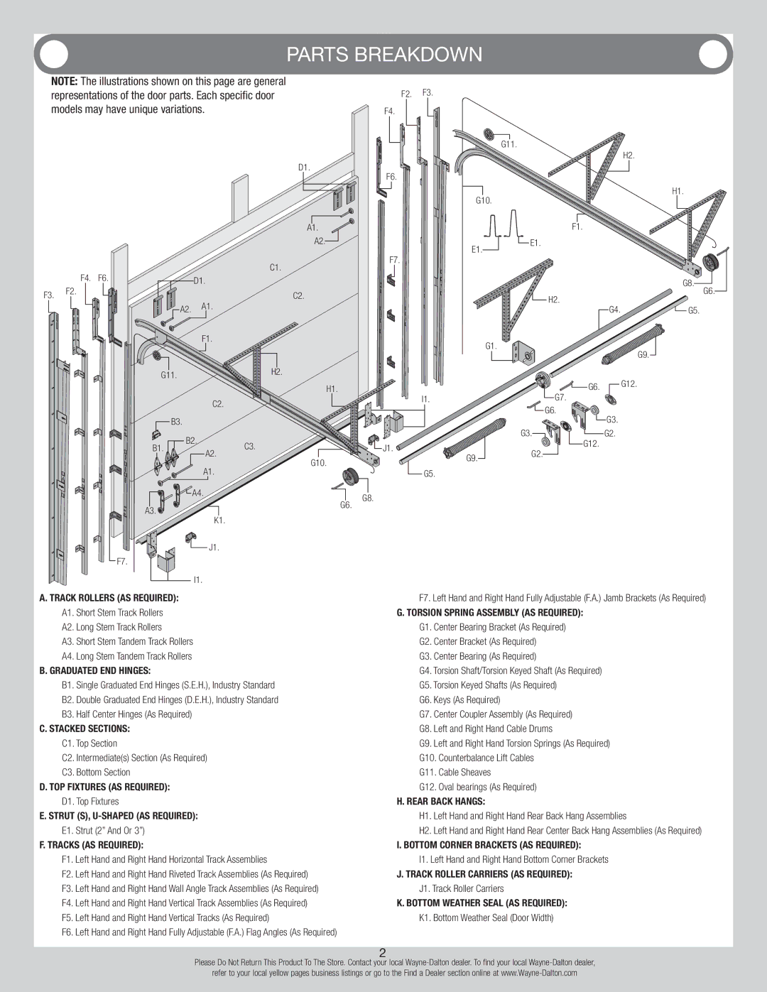
NOTE: The illustrations shown on this page are general representations of the door parts. Each specific door models may have unique variations.
D1.
F2. F3.
F4.
G11.
H2.
F6.
 H1. G10.
|
|
|
|
| A1. |
|
|
|
|
| A2. |
|
|
|
|
| E1. |
|
|
|
|
| F7. |
| F4. | F6. |
|
| C1. |
|
| D1. |
| ||
|
|
|
|
| |
F3. | F2. |
|
|
| C2. |
|
|
|
| ||
|
|
| A2. | A1. |
|
|
|
|
|
| |
|
|
|
| F1. | G1. |
|
|
|
|
|
G11. |
|
| H2. |
|
|
|
|
|
|
| |
|
|
| H1. |
| I1. |
| C2. |
|
|
| |
|
|
|
|
| |
B3. |
|
|
|
|
|
B1. | B2. | C3. |
|
| J1. |
A2. |
|
| |||
|
| G10. |
| G9. | |
|
|
|
| ||
| A1. |
|
|
| |
|
|
|
| G5. | |
| A4. |
|
|
| G8. |
|
|
|
| G6. | |
A3. |
|
|
|
| |
K1. |
|
|
|
| |
|
|
|
|
| |
| J1. |
|
|
|
|
F7. |
|
|
|
|
|
| I1. |
|
|
|
|
F1.
![]() E1.
E1.
| G8. | G6. |
H2. |
| |
|
| |
G4. | G5. |
|
G9. ![]()
| G6. | G12. |
|
| |
| G7. |
|
| G6. | G3. |
|
| |
G3. | G12. | G2. |
G2. |
| |
|
|
A. Track Rollers (As Required): | F7. Left Hand and Right Hand Fully Adjustable (F.A.) Jamb Brackets (As Required) | ||
A1. | Short Stem Track Rollers | G. Torsion Spring Assembly (As Required): | |
A2. | Long Stem Track Rollers | G1. | Center Bearing Bracket (As Required) |
A3. | Short Stem Tandem Track Rollers | G2. | Center Bracket (As Required) |
A4. | Long Stem Tandem Track Rollers | G3. | Center Bearing (As Required) |
B. Graduated End Hinges: | G4. Torsion Shaft/Torsion Keyed Shaft (As Required) | ||
B1. | Single Graduated End Hinges (S.E.H.), Industry Standard | G5. Torsion Keyed Shafts (As Required) | |
B2. | Double Graduated End Hinges (D.E.H.), Industry Standard | G6. | Keys (As Required) |
B3. | Half Center Hinges (As Required) | G7. | Center Coupler Assembly (As Required) |
C. Stacked Sections: | G8. Left and Right Hand Cable Drums | ||
C1. Top Section | G9. | Left and Right Hand Torsion Springs (As Required) | |
C2. Intermediate(s) Section (As Required) | G10. Counterbalance Lift Cables | ||
C3. Bottom Section | G11. Cable Sheaves | ||
D. Top Fixtures (As Required): | G12. Oval bearings (As Required) | ||
D1. Top Fixtures | H. Rear Back Hangs: | ||
E. Strut (s), | H1. Left Hand and Right Hand Rear Back Hang Assemblies | ||
E1. Strut (2” And Or 3”) | H2. Left Hand and Right Hand Rear Center Back Hang Assemblies (As Required) | ||
F. Tracks (As Required): | I. Bottom Corner Brackets (As Required): | ||
F1. | Left Hand and Right Hand Horizontal Track Assemblies | I1. Left Hand and Right Hand Bottom Corner Brackets | |
F2. | Left Hand and Right Hand Riveted Track Assemblies (As Required) | J. Track Roller Carriers (As Required): | |
F3. | Left Hand and Right Hand Wall Angle Track Assemblies (As Required) | J1. Track Roller Carriers | |
F4. | Left Hand and Right Hand Vertical Track Assemblies (As Required) | K. Bottom Weather Seal (As Required): | |
F5. | Left Hand and Right Hand Vertical Tracks (As Required) | K1. Bottom Weather Seal (Door Width) | |
F6. | Left Hand and Right Hand Fully Adjustable (F.A.) Flag Angles (As Required) |
|
|
2
Please Do Not Return This Product To The Store. Contact your local
refer to your local yellow pages business listings or go to the Find a Dealer section online at