first, then through the rear support bracket and the
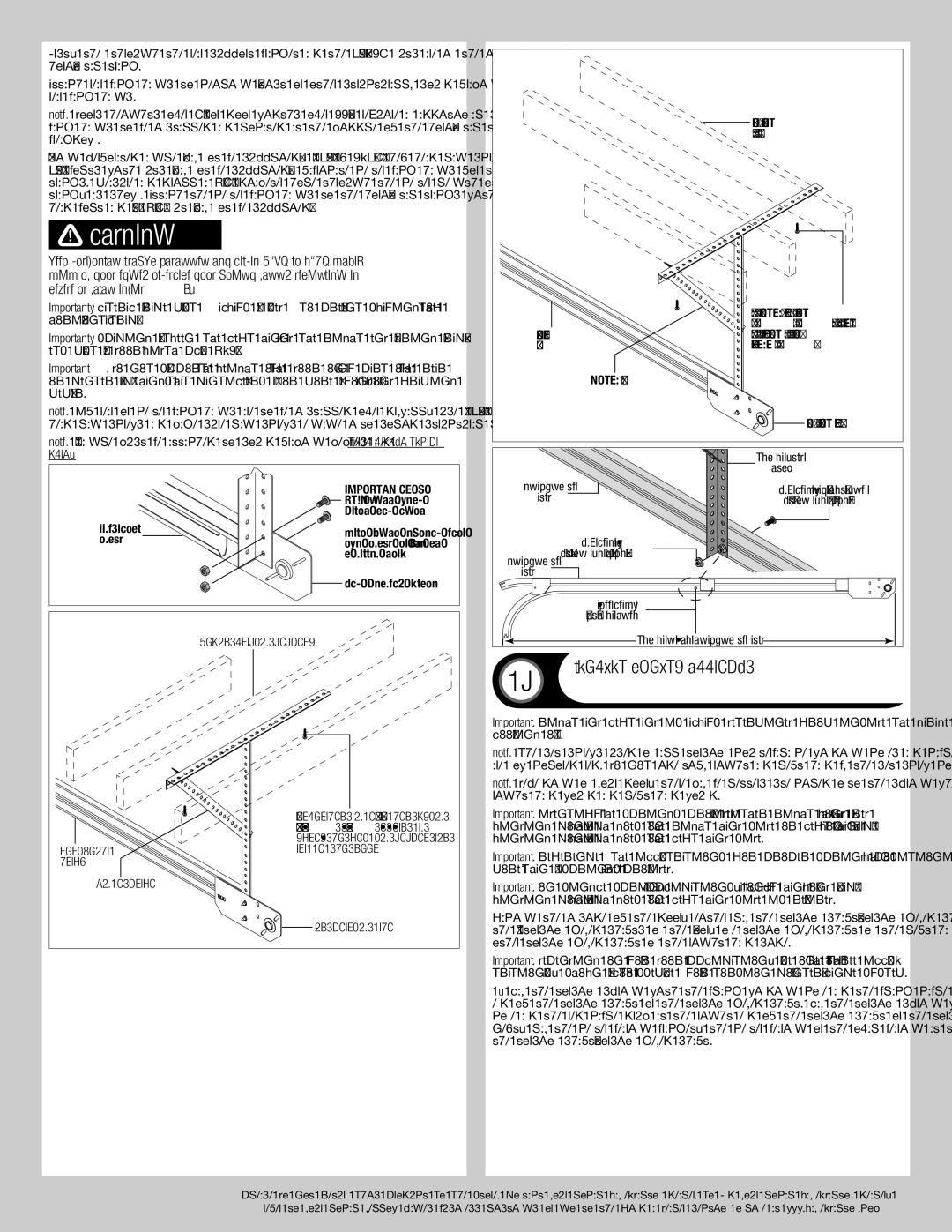
Attach rear back hangs to ceiling joist or other structurally sound framing members. Brace rear back hangs.
NOTE: Doors heights over 8’0” or door widths over 11’0”, require an additional set of center back hangs to be installed and located at the middle of the horizontal tracks, see parts breakdown.
Using perforated angle (may not be supplied), (2) 5/16” x
![]() WARNING
WARNING
Keep horizontal tracks parallel and within 3/4” to 7/8” maxi- mum of door edge, otherwise door could fall, resulting in severe or fatal injury.
IMPORTANT! Lateral brace must always be used to prevent swaying of the horizontal track.
IMPORTANT! Spacing between the left hand and the right end bearing brack- ets must be door width plus
Important: Do not support the weight of the door on any part of the rear or center back hangs that cantilevers 4” or more beyond a sound framing member.
Note: If rear or center back hangs are to be installed over drywall, use (2) 5/16” x 2” hex head lag screws and make sure lag screws engage into solid structural lumber.
Horizontal track
Angle brace
Sound framing members
Perforated angle- Bolted using
(2) 5/16” x
End bearing plate
Note: 26” angle must be attached to sound framing members and nails should not be used.
| (2) | |
| 3/4” Truss head | |
| bolts and nuts | |
Horizontal | Bolt must extend into | |
track | ||
the track to serve as | ||
| a roller stop | |
| End bearing plate | |
| Sound framing members |
Perforated angle- Bolted using
(2) 5/16” x
Horizontalparallel to door track
Angle brace
End bearing plate
|
| Center back |
|
| hang |
Horizontal | (1) 3/8” Truss head bolt | |
track |
| (may not be supplied) |
|
| (1) 3/8” Nut |
Horizontal | (may not be supplied) | |
|
| |
track |
|
|
|
| Drill 3/8” |
|
| diameter hole |
|
| Center of the horizontal track |
19 |
| Torsion Spring Assembly |
| Tools: Ratchet Wrench, 3/8” Socket, 3/8”,9/16” Wrench | |
IMPORTANT: RIGHT AND LEFT AND IS ALWAYS DETERMINED FROM INSIDE THE GARAGE LOOKING OUT.
NOTE: The set screws used on all torsion counterbalance winding cones and cable drums, are now colored red. DO NOT identify right and left hand by the set screw color.
NOTE: Depending on your door, there may be letters stenciled onto the spring which refer to right hand wound and left hand wound.
IMPORTANT: Identify the springs provided as either right hand wound (red winding cone), which goes on the RIGHT HAND SIDE or left hand wound (black winding cone), which goes on the LEFT HAND SIDE.
IMPORTANT: Reference the illustrations for proper spring positioning when more than 2 springs are provided.
IMPORTANT: On single spring applications, only a left hand wound (black winding cone), which goes on the LEFT HAND SIDE is required.
Facing the inside of the door, either lay the torsion shaft/torsion keyed shaft on the floor or lay the (2) torsion keyed shafts on the floor, one torsion keyed shaft on the left hand side and the other torsion keyed shaft on the right hand side.
IMPORTANT: Depending on your door application, use one of the three illus- tration’s, shown below to assemble your torsion counterbalance system.
1.Lay the torsion spring with the black winding cone and the black cable drum at the left end of the torsion shaft or the torsion keyed shaft. Lay the torsion spring with the red winding cone and the red cable drum at the right end of the torsion shaft or the torsion keyed shaft. Next, lay the center bearing bracket, the center bearing or the oval bearing at the center of the torsion shaft/torsion keyed shaft.
12
Please Do Not Return This Product To The Store. Contact your local
refer to your local yellow pages business listings or go to the Find a Dealer section online at