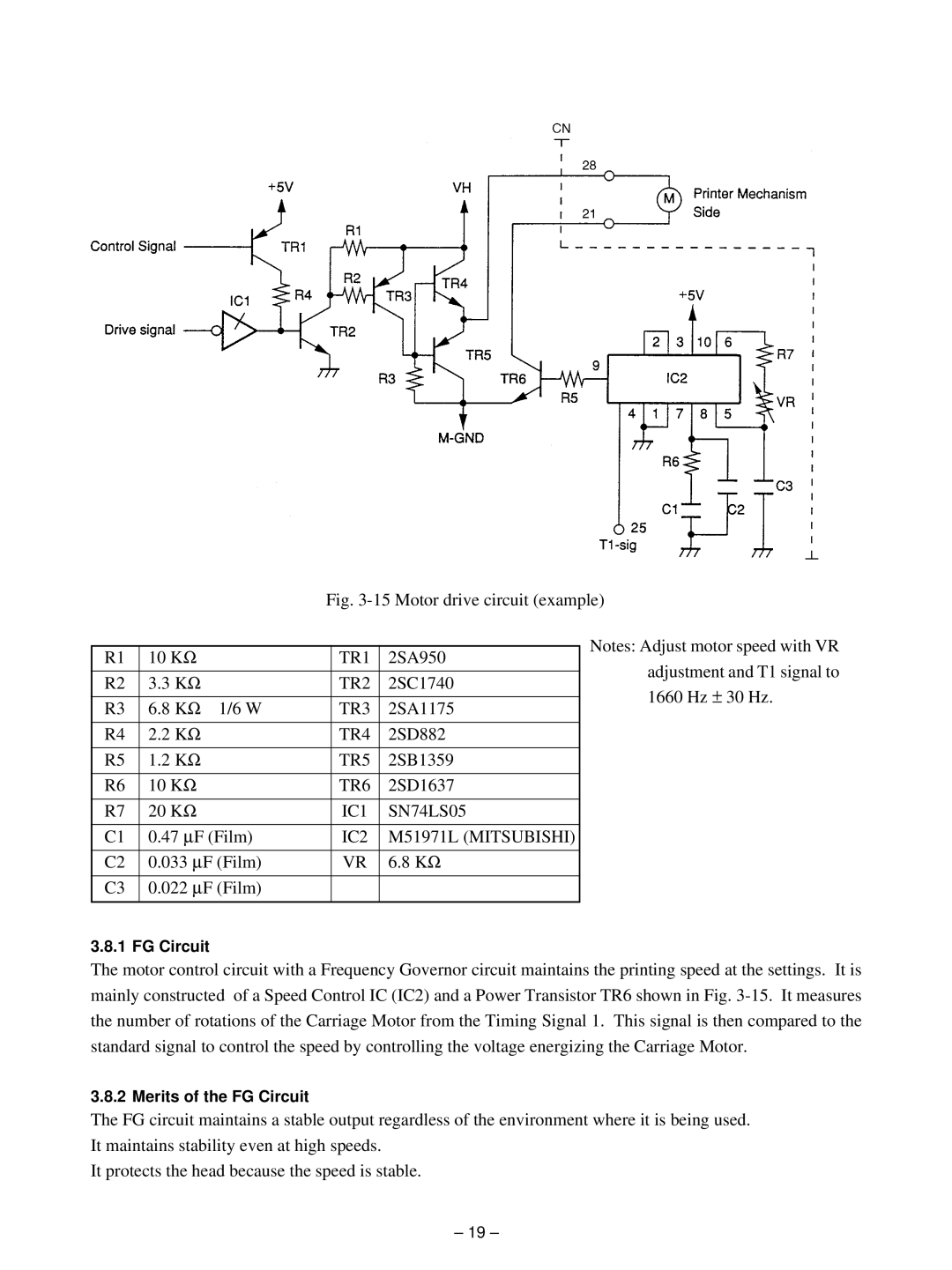
Fig. 3-15 Motor drive circuit (example)
|
|
|
|
| Notes: Adjust motor speed with VR | |
R1 | 10 KΩ |
| TR1 | 2SA950 | ||
| adjustment and T1 signal to | |||||
|
|
|
|
| ||
R2 | 3.3 KΩ |
| TR2 | 2SC1740 | ||
| 1660 Hz ± 30 Hz. | |||||
|
|
|
|
| ||
R3 | 6.8 KΩ | 1/6 W | TR3 | 2SA1175 | ||
| ||||||
|
|
|
|
|
| |
R4 | 2.2 KΩ |
| TR4 | 2SD882 |
| |
|
|
|
|
|
| |
R5 | 1.2 KΩ |
| TR5 | 2SB1359 |
| |
|
|
|
|
|
| |
R6 | 10 KΩ |
| TR6 | 2SD1637 |
| |
|
|
|
|
|
| |
R7 | 20 KΩ |
| IC1 | SN74LS05 |
| |
|
|
|
|
|
| |
C1 | 0.47 ∝ | F (Film) | IC2 | M51971L (MITSUBISHI) |
| |
|
|
|
|
| ||
C2 | 0.033 ∝ F (Film) | VR | 6.8 KΩ |
| ||
|
|
|
|
| ||
C3 | 0.022 ∝ F (Film) |
|
|
| ||
|
|
|
|
|
| |
3.8.1 FG Circuit
The motor control circuit with a Frequency Governor circuit maintains the printing speed at the settings. It is mainly constructed of a Speed Control IC (IC2) and a Power Transistor TR6 shown in Fig.
3.8.2 Merits of the FG Circuit
The FG circuit maintains a stable output regardless of the environment where it is being used. It maintains stability even at high speeds.
It protects the head because the speed is stable.
– 19 –