7. INSTALLATION
1.At the time of mounting the printer mechanism into its housing cabinet, put cushion material, such as, rubber foot, on the printer mechanism legs. If installed directly, reverberations occur producing noise. We recommend that you use the following rubber foot.
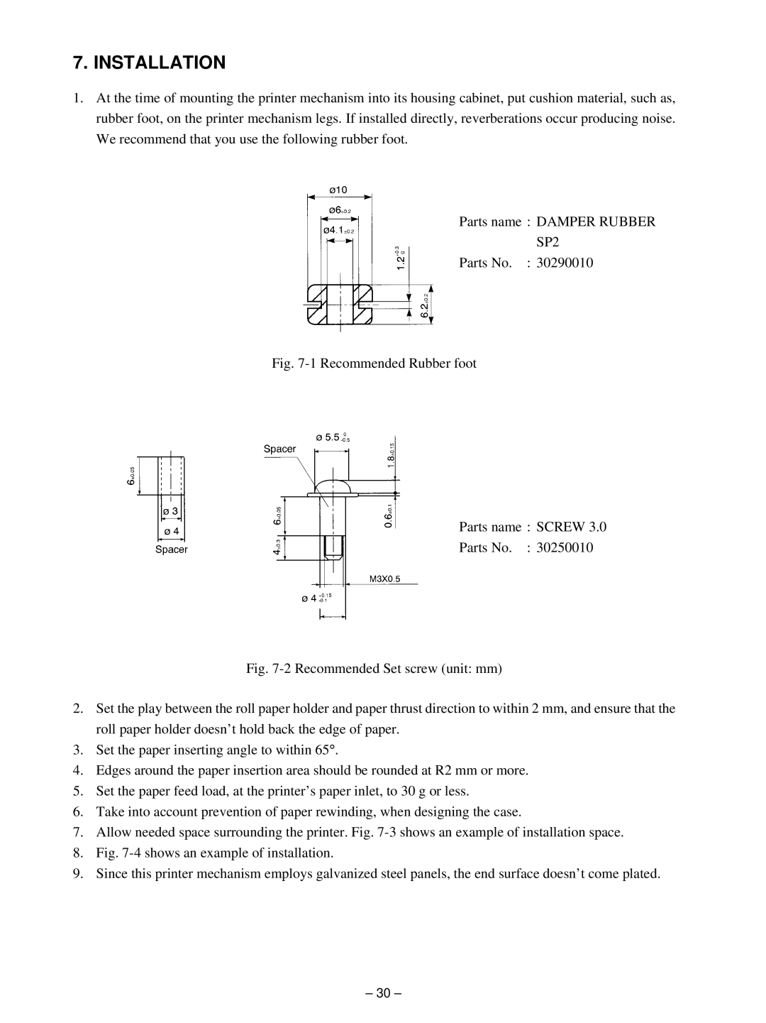
Parts name : DAMPER RUBBER
SP2
Parts No. : 30290010
Fig. 7-1 Recommended Rubber foot
Parts name : SCREW 3.0
Parts No. : 30250010
Fig. 7-2 Recommended Set screw (unit: mm)
2.Set the play between the roll paper holder and paper thrust direction to within 2 mm, and ensure that the roll paper holder doesn’t hold back the edge of paper.
3.Set the paper inserting angle to within 65° .
4.Edges around the paper insertion area should be rounded at R2 mm or more.
5.Set the paper feed load, at the printer’s paper inlet, to 30 g or less.
6.Take into account prevention of paper rewinding, when designing the case.
7.Allow needed space surrounding the printer. Fig. 7-3 shows an example of installation space.
8.Fig. 7-4 shows an example of installation.
9.Since this printer mechanism employs galvanized steel panels, the end surface doesn’t come plated.
– 30 –