M4 x 0.7
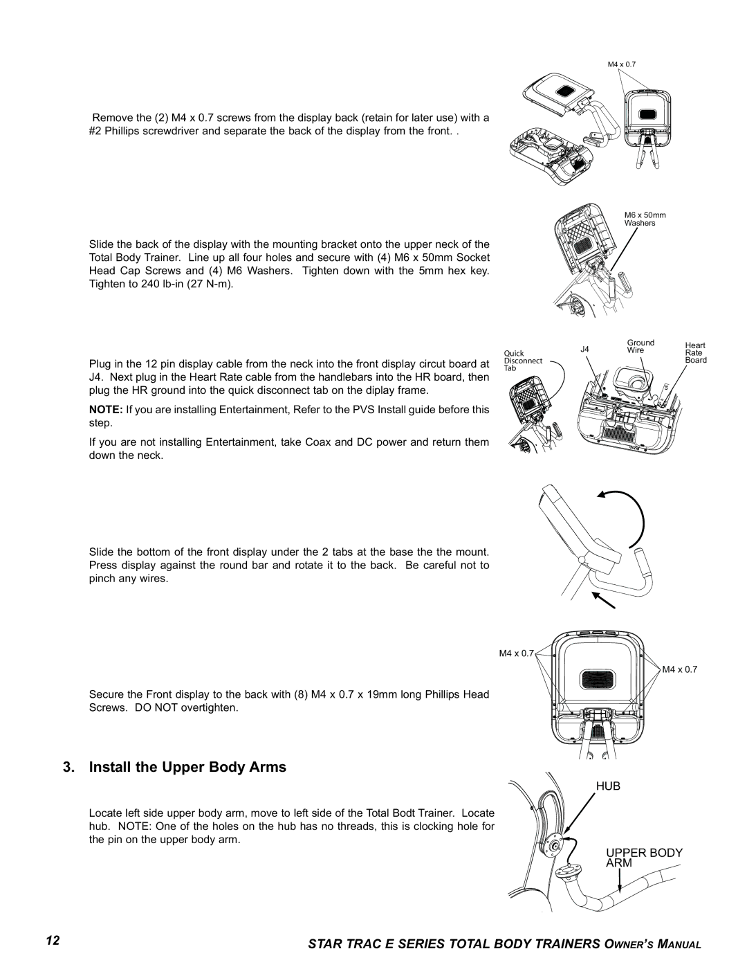
Remove the (2) M4 x 0.7 screws from the display back (retain for later use) with a #2 Phillips screwdriver and separate the back of the display from the front. .
M6 x 50mm
Washers
Slide the back of the display with the mounting bracket onto the upper neck of the
Total Body Trainer. Line up all four holes and secure with (4) M6 x 50mm Socket
Head Cap Screws and (4) M6 Washers. Tighten down with the 5mm hex key.
Tighten to 240
Plug in the 12 pin display cable from the neck into the front display circut board at J4. Next plug in the Heart Rate cable from the handlebars into the HR board, then plug the HR ground into the quick disconnect tab on the diplay frame.
NOTE: If you are installing Entertainment, Refer to the PVS Install guide before this step.
If you are not installing Entertainment, take Coax and DC power and return them down the neck.
Slide the bottom of the front display under the 2 tabs at the base the the mount. Press display against the round bar and rotate it to the back. Be careful not to pinch any wires.
| J4 | Ground | Heart |
Quick | Wire | Rate | |
Disconnect |
|
| Board |
Tab |
|
|
|
M4 x 0.7
M4 x 0.7
Secure the Front display to the back with (8) M4 x 0.7 x 19mm long Phillips Head
Screws. DO NOT overtighten.
3. Install the Upper Body Arms
HUB
Locate left side upper body arm, move to left side of the Total Bodt Trainer. Locate hub. NOTE: One of the holes on the hub has no threads, this is clocking hole for the pin on the upper body arm.
UPPER BODY
ARM
12 | STAR TRAC E SERIES TOTAL BODY TRAINERS OWNER’S MANUAL |