Hardware Setup
2
1.Connect the power supply to the NETRS232 and to AC power.
2.The power (red) LED will light to indicate that the unit is receiving power.
3.Connect a network cable to the Ethernet
•an Ethernet hub or switch, using a length of standard Ethernet network cable
•a host PC directly, using an Ethernet
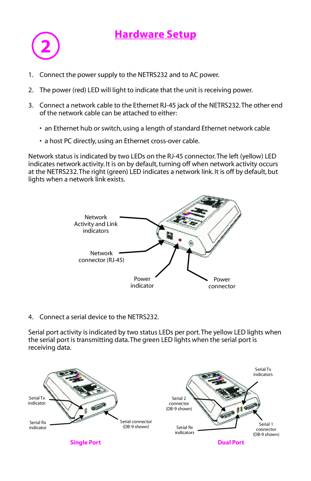
Network status is indicated by two LEDs on the
Network
Activity and Link
indicators
Network ![]() connector
connector
Power | Power |
indicator | connector |
4. Connect a serial device to the NETRS232.
Serial port activity is indicated by two status LEDs per port. The yellow LED lights when the serial port is transmitting data. The green LED lights when the serial port is receiving data.
|
|
| Serial Tx | |
|
|
| indicators | |
Serial Tx |
| Serial 2 |
| |
indicator |
| connector |
| |
|
|
| ||
Serial Rx | Serial connector |
| Serial 1 | |
indicator | Serial Rx | |||
connector | ||||
|
| indicators | ||
|
| |||
|
|
|
Single Port | Dual Port |