barb, use a wire tie or hose clamp (not supplied with kit) and secure.

6.Take the other end of the flexible tubing and slide it through the hose clamp on the jacket top cover and install it into one of the four barb fittings in vent pipe assembly #2.

7.Once installed along with the rest of the vent configuration, make sure to operate the unit through at least one heat up cycle to ensure there is no leakage around the hose barb or any joints of the VAA or vent pipe system.

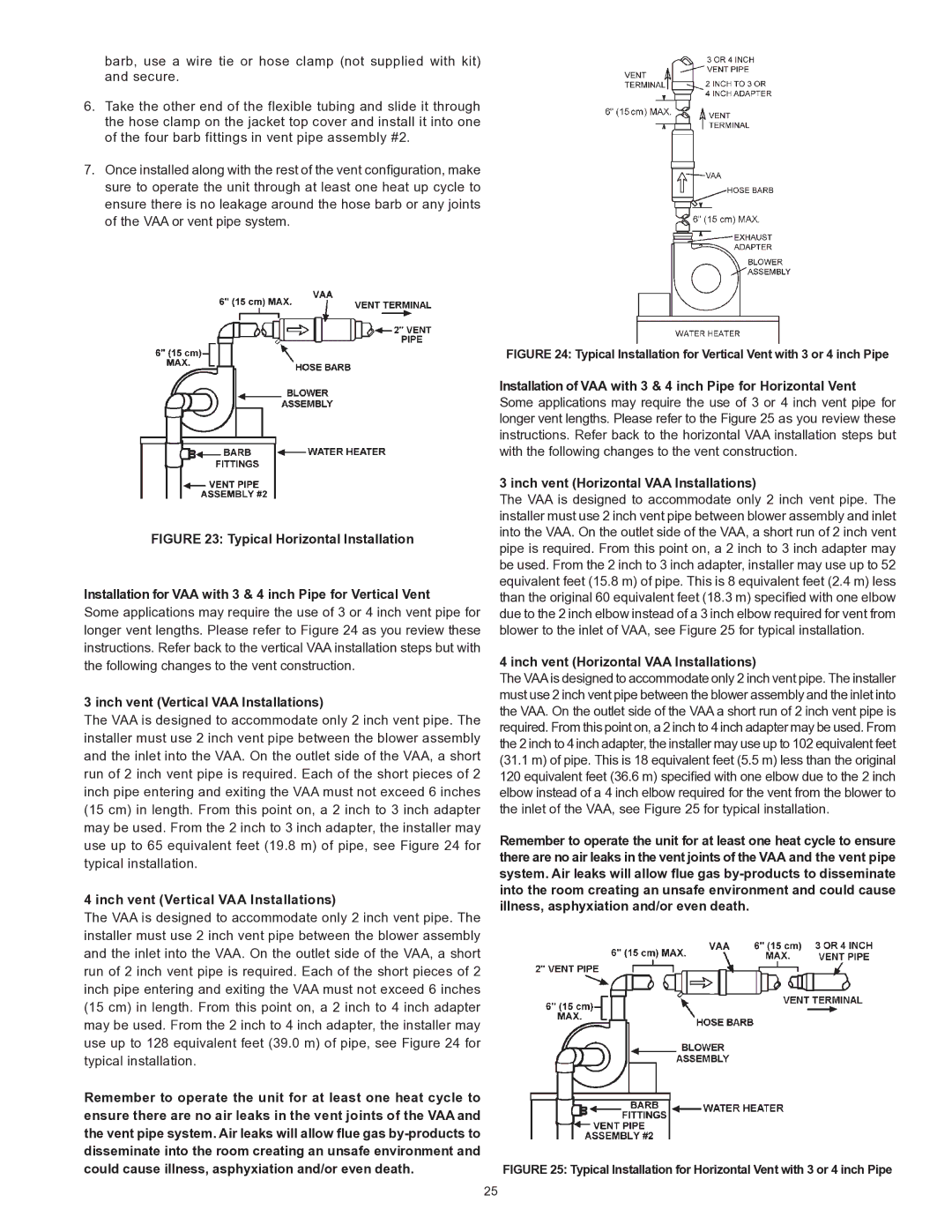
FIGURE 23: Typical Horizontal Installation

Installation for VAA with 3 & 4 inch Pipe for Vertical Vent

Some applications may require the use of 3 or 4 inch vent pipe for longer vent lengths. Please refer to Figure 24 as you review these instructions. Refer back to the vertical VAA installation steps but with the following changes to the vent construction.

3 inch vent (Vertical VAA Installations)

The VAA is designed to accommodate only 2 inch vent pipe. The installer must use 2 inch vent pipe between the blower assembly and the inlet into the VAA. On the outlet side of the VAA, a short run of 2 inch vent pipe is required. Each of the short pieces of 2 inch pipe entering and exiting the VAA must not exceed 6 inches (15 cm) in length. From this point on, a 2 inch to 3 inch adapter may be used. From the 2 inch to 3 inch adapter, the installer may use up to 65 equivalent feet (19.8 m) of pipe, see Figure 24 for typical installation.

4 inch vent (Vertical VAA Installations)

The VAA is designed to accommodate only 2 inch vent pipe. The installer must use 2 inch vent pipe between the blower assembly and the inlet into the VAA. On the outlet side of the VAA, a short run of 2 inch vent pipe is required. Each of the short pieces of 2 inch pipe entering and exiting the VAA must not exceed 6 inches (15 cm) in length. From this point on, a 2 inch to 4 inch adapter may be used. From the 2 inch to 4 inch adapter, the installer may use up to 128 equivalent feet (39.0 m) of pipe, see Figure 24 for typical installation.

Remember to operate the unit for at least one heat cycle to ensure there are no air leaks in the vent joints of the VAA and the vent pipe system. Air leaks will allow flue gas by-products to disseminate into the room creating an unsafe environment and could cause illness, asphyxiation and/or even death.

FIGURE 24: Typical Installation for Vertical Vent with 3 or 4 inch Pipe

Installation of VAA with 3 & 4 inch Pipe for Horizontal Vent Some applications may require the use of 3 or 4 inch vent pipe for longer vent lengths. Please refer to the Figure 25 as you review these instructions. Refer back to the horizontal VAA installation steps but with the following changes to the vent construction.

3 inch vent (Horizontal VAA Installations)

The VAA is designed to accommodate only 2 inch vent pipe. The installer must use 2 inch vent pipe between blower assembly and inlet into the VAA. On the outlet side of the VAA, a short run of 2 inch vent pipe is required. From this point on, a 2 inch to 3 inch adapter may be used. From the 2 inch to 3 inch adapter, installer may use up to 52 equivalent feet (15.8 m) of pipe. This is 8 equivalent feet (2.4 m) less than the original 60 equivalent feet (18.3 m) specified with one elbow due to the 2 inch elbow instead of a 3 inch elbow required for vent from blower to the inlet of VAA, see Figure 25 for typical installation.

4 inch vent (Horizontal VAA Installations)

The VAA is designed to accommodate only 2 inch vent pipe. The installer must use 2 inch vent pipe between the blower assembly and the inlet into the VAA. On the outlet side of the VAA a short run of 2 inch vent pipe is required. From this point on, a 2 inch to 4 inch adapter may be used. From the 2 inch to 4 inch adapter, the installer may use up to 102 equivalent feet (31.1 m) of pipe. This is 18 equivalent feet (5.5 m) less than the original 120 equivalent feet (36.6 m) specified with one elbow due to the 2 inch elbow instead of a 4 inch elbow required for the vent from the blower to the inlet of the VAA, see Figure 25 for typical installation.

Remember to operate the unit for at least one heat cycle to ensure there are no air leaks in the vent joints of the VAA and the vent pipe system. Air leaks will allow flue gas by-products to disseminate into the room creating an unsafe environment and could cause illness, asphyxiation and/or even death.

FIGURE 25: Typical Installation for Horizontal Vent with 3 or 4 inch Pipe

25

Page 25
Image 25
State Industries 197425-004 instruction manual Inch vent Vertical VAA Installations

197425-004 specifications

State Industries Model 197425-004 is a noteworthy water heater designed to cater to the needs of both residential and commercial applications. Known for its efficiency and reliability, this model offers a range of features that enhance its appeal to users looking for an effective water heating solution.

One of the primary characteristics of the 197425-004 is its tankless design, which allows for an endless supply of hot water. Unlike traditional water heaters that store hot water in a tank, this model heats water on demand, conserving both energy and space. This is particularly advantageous for households or businesses with fluctuating hot water needs, as it eliminates the risk of running out of hot water during peak usage times.

The technology behind the State Industries 197425-004 incorporates advanced insulation and heat exchange systems, which significantly improve energy efficiency. With a high energy factor rating, this unit minimizes energy consumption, thus reducing utility bills and environmental impact. Users can expect lower operating costs without sacrificing performance, making it a cost-effective option in the long run.

Another defining feature of the 197425-004 is its durable construction. Built with high-quality materials, including corrosion-resistant components, this water heater is designed for longevity. The model also includes a user-friendly digital thermostat, enabling precise temperature control and easy monitoring. This ensures that users can customize their hot water needs according to individual preferences.

In addition to its performance and efficiency, the State Industries 197425-004 prioritizes safety. It is equipped with multiple safety features such as thermal overload protection and precise temperature regulation, reducing the risk of accidents.

Installation is made convenient with this model, as it is compatible with various plumbing systems and does not require complex modifications. Its compact size allows for flexible installation options, whether it is placed indoors or outdoors, depending on user preferences.

In summary, the State Industries 197425-004 represents a perfect blend of cutting-edge technology, energy efficiency, and durability. With its tankless heating system, impressive energy factor, and safety features, it continues to stand out as an excellent choice for reliable hot water solutions in diverse settings.