Sterling SSV 05 operating instructions SSV Installing the control and maintenance unit

Models: SSV 05

1 34
Download 34 pages 4.44 Kb
Page 17
Image 17

SSV 05

2.3. Installing the control and maintenance unit

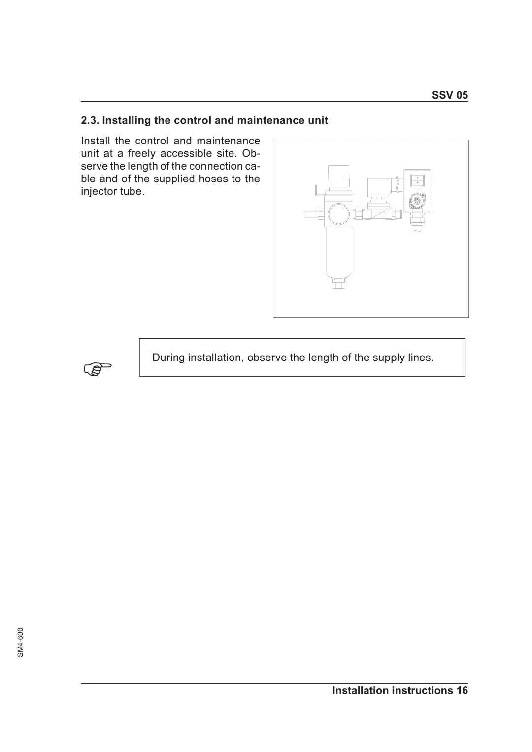
Install the control and maintenance unit at a freely accessible site. Ob- serve the length of the connection ca- ble and of the supplied hoses to the injector tube.

1

0

F

During installation, observe the length of the supply lines.

SM4-600

Installation instructions 16

Page 17
Image 17
Sterling SSV 05 operating instructions SSV Installing the control and maintenance unit