ENGLISHGB

SYMBOLS

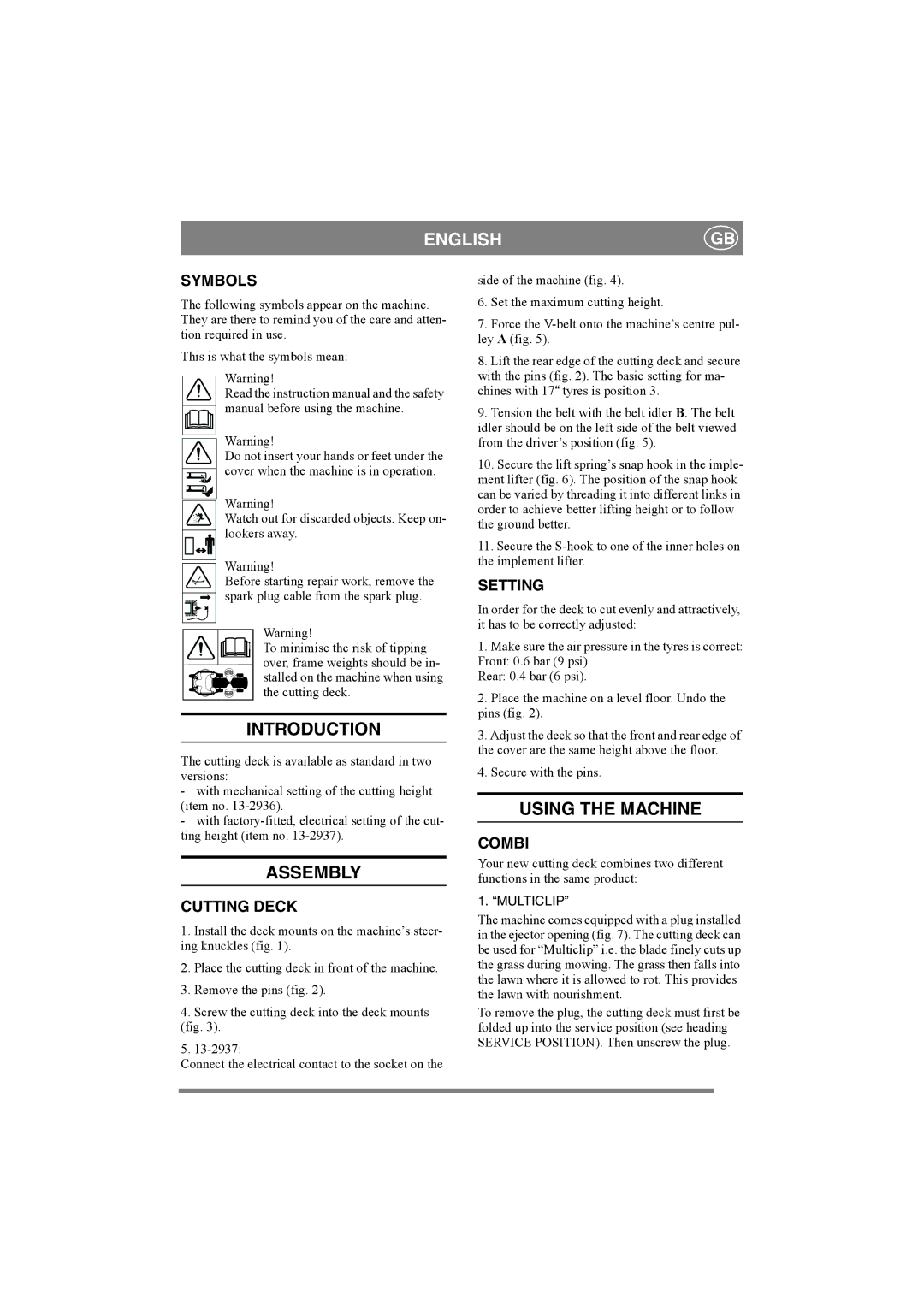
The following symbols appear on the machine. They are there to remind you of the care and atten- tion required in use.

This is what the symbols mean:

Warning!

Read the instruction manual and the safety manual before using the machine.

Warning!

Do not insert your hands or feet under the cover when the machine is in operation.

Warning!

Watch out for discarded objects. Keep on- lookers away.

Warning!

Before starting repair work, remove the spark plug cable from the spark plug.

Warning!

To minimise the risk of tipping over, frame weights should be in- stalled on the machine when using the cutting deck.

side of the machine (fig. 4).

6.Set the maximum cutting height.

7.Force the V-belt onto the machine’s centre pul- ley A (fig. 5).

8.Lift the rear edge of the cutting deck and secure with the pins (fig. 2). The basic setting for ma- chines with 17tyres is position 3.

9.Tension the belt with the belt idler B. The belt idler should be on the left side of the belt viewed from the driver’s position (fig. 5).

10.Secure the lift spring’s snap hook in the imple- ment lifter (fig. 6). The position of the snap hook can be varied by threading it into different links in order to achieve better lifting height or to follow the ground better.

11.Secure the S-hook to one of the inner holes on the implement lifter.

SETTING

In order for the deck to cut evenly and attractively, it has to be correctly adjusted:

1.Make sure the air pressure in the tyres is correct: Front: 0.6 bar (9 psi).

Rear: 0.4 bar (6 psi).

2.Place the machine on a level floor. Undo the pins (fig. 2).

INTRODUCTION

The cutting deck is available as standard in two versions:

-with mechanical setting of the cutting height (item no. 13-2936).

-with factory-fitted, electrical setting of the cut- ting height (item no. 13-2937).

ASSEMBLY

CUTTING DECK

1.Install the deck mounts on the machine’s steer- ing knuckles (fig. 1).

2.Place the cutting deck in front of the machine.

3.Remove the pins (fig. 2).

4.Screw the cutting deck into the deck mounts (fig. 3).

5.13-2937:

Connect the electrical contact to the socket on the

3.Adjust the deck so that the front and rear edge of the cover are the same height above the floor.

4.Secure with the pins.

USING THE MACHINE

COMBI

Your new cutting deck combines two different functions in the same product:

1. “MULTICLIP”

The machine comes equipped with a plug installed in the ejector opening (fig. 7). The cutting deck can be used for “Multiclip” i.e. the blade finely cuts up the grass during mowing. The grass then falls into the lawn where it is allowed to rot. This provides the lawn with nourishment.

To remove the plug, the cutting deck must first be folded up into the service position (see heading SERVICE POSITION). Then unscrew the plug.

Page 4
Image 4
Stiga 125 COMBI PRO manual Introduction, Assembly, Using the Machine

125 COMBI PRO specifications

The Stiga 125 COMBI PRO is a versatile and powerful lawn mower designed for those who take their gardening seriously. With a combination of innovative features and robust engineering, this machine is well-suited for handling various types of lawns, ensuring an efficient and enjoyable mowing experience.

At the heart of the Stiga 125 COMBI PRO is its reliable and efficient 125cc engine. This small but powerful engine delivers consistent performance, making it capable of tackling uneven terrains and thick grass with ease. The mower is equipped with a user-friendly recoil start system, ensuring that starting up is as simple as pulling a cord.

One of the standout features of the Stiga 125 COMBI PRO is its cutting system, which offers three different functions: collecting, mulching, and rear discharge. This versatility allows users to choose the most suitable mowing method for their lawn conditions. The spacious 40-liter grass collector ensures that you can mow for longer without needing to stop and empty the bag frequently. For those eco-conscious gardeners, the mulching option finely chops the grass clippings and returns them to the lawn, acting as a natural fertilizer.

The cutting width of 41 cm allows for efficient mowing, even in tighter spaces. The mower features an adjustable cutting height that can be set between 25mm to 75mm. This customization ensures that users can achieve their desired lawn finish, whether they prefer a close cut or a longer, more natural look.

The Stiga 125 COMBI PRO also boasts ergonomic features designed for comfort during operation. The adjustable handlebar can be tailored to the user’s height, minimizing strain during long mowing sessions. The mower’s lightweight design further enhances maneuverability, allowing for easy navigation around flower beds and garden obstacles.

Additionally, the mower's durable construction represents a commitment to longevity. Quality materials and a sturdy chassis ensure that the Stiga 125 COMBI PRO can withstand regular use and challenging conditions over time.

In summary, the Stiga 125 COMBI PRO combines power, versatility, and user-centric features, making it an ideal choice for homeowners looking to maintain a pristine lawn. Its reliable engine, flexible cutting options, and ergonomic design set it apart as a valuable tool in any gardening arsenal. Whether you're a seasoned gardener or a novice, this mower promises to deliver exceptional performance and ease of use for all your lawn care needs.