Installation | 13 |
|
|
SCSI
ID
| FAC | TOR |
|
|
W |
|
|
| |
| Y | NE |
| |
A |
| W | ||
| RN |
|
| |
| ING |
|
| |
0541A
Drive
(Not Included)
5.25" Drive
Mounting
Bracket
ID Select
Cable
I/O Cable
Power
Connector
Terminator
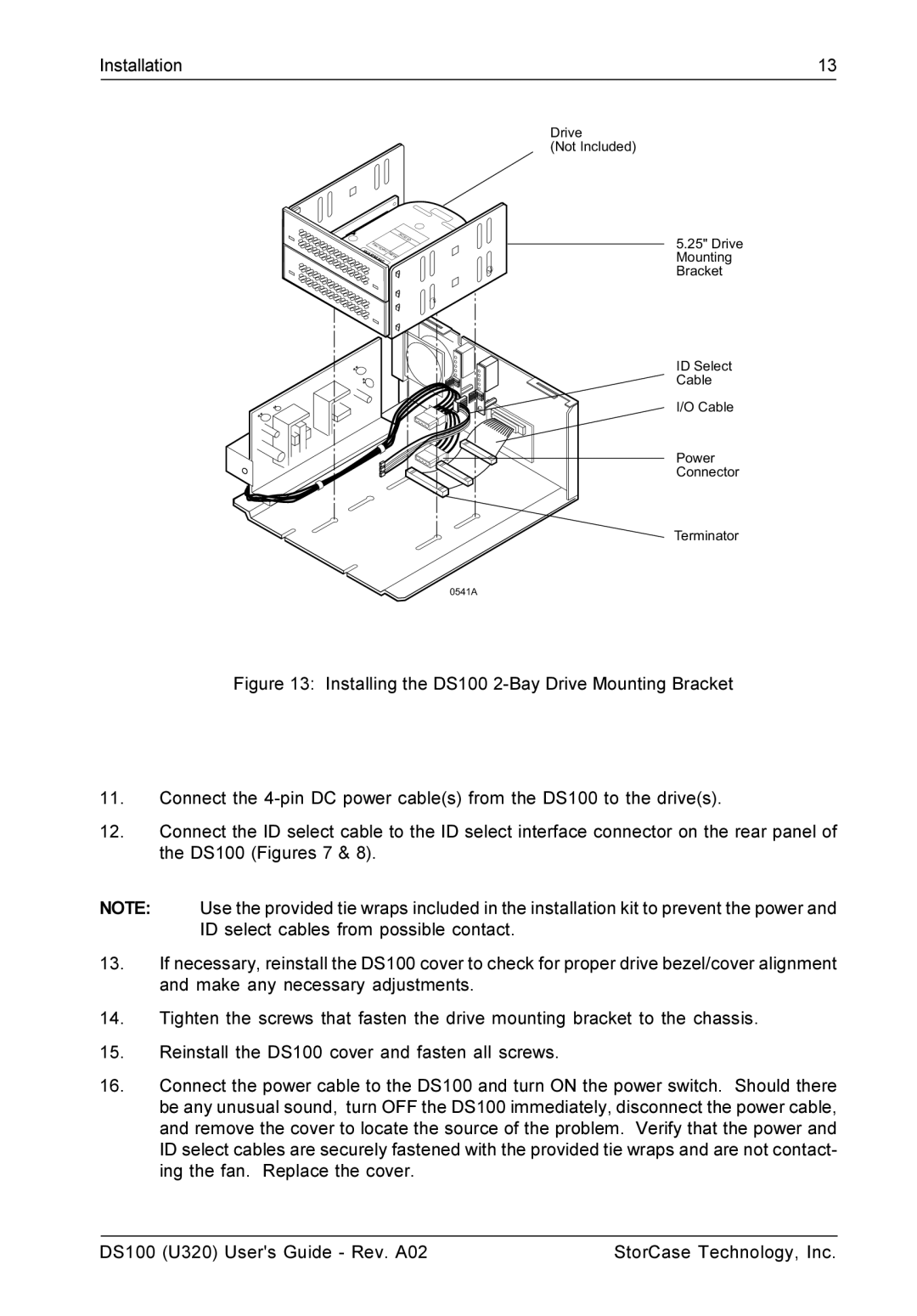
Figure 13: Installing the DS100 2-Bay Drive Mounting Bracket
11.Connect the 4-pin DC power cable(s) from the DS100 to the drive(s).
12.Connect the ID select cable to the ID select interface connector on the rear panel of the DS100 (Figures 7 & 8).
NOTE: Use the provided tie wraps included in the installation kit to prevent the power and ID select cables from possible contact.
13.If necessary, reinstall the DS100 cover to check for proper drive bezel/cover alignment and make any necessary adjustments.
14.Tighten the screws that fasten the drive mounting bracket to the chassis.
15.Reinstall the DS100 cover and fasten all screws.
16.Connect the power cable to the DS100 and turn ON the power switch. Should there be any unusual sound, turn OFF the DS100 immediately, disconnect the power cable, and remove the cover to locate the source of the problem. Verify that the power and ID select cables are securely fastened with the provided tie wraps and are not contact- ing the fan. Replace the cover.
DS100 (U320) User's Guide - Rev. A02 | StorCase Technology, Inc. |
