This section is intended to assist the operator with the initial
DO NOT use your mixer until this section is thoroughly understood.
MS-40M — INITIAL START-UP
STARTING THE ENGINE (gasoline only)
The following steps outline the procedure for starting the engine. Depending on the type of engine employed in the mixer the steps may vary slightly. If your mixer has an electric motor disregard this section.
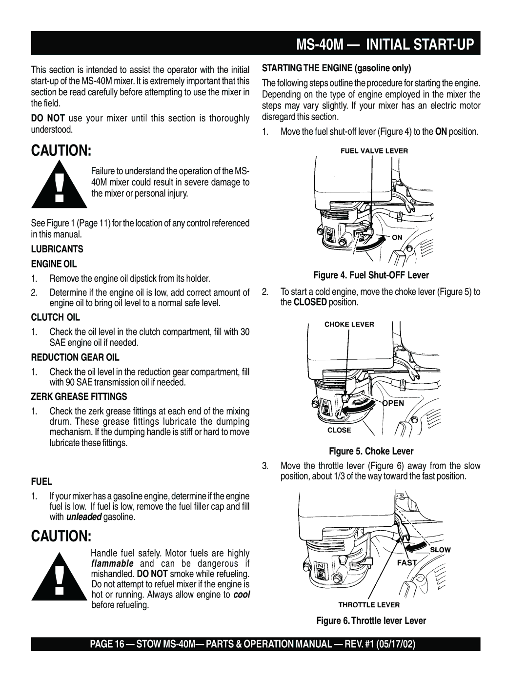
1.Move the fuel shut-off lever (Figure 4) to the ON position.
CAUTION:
Failure to understand the operation of the MS- 40M mixer could result in severe damage to the mixer or personal injury.
See Figure 1 (Page 11) for the location of any control referenced in this manual.
LUBRICANTS
ENGINE OIL
1.Remove the engine oil dipstick from its holder.
2.Determine if the engine oil is low, add correct amount of engine oil to bring oil level to a normal safe level.
CLUTCH OIL
1.Check the oil level in the clutch compartment, fill with 30 SAE engine oil if needed.
REDUCTION GEAR OIL
1.Check the oil level in the reduction gear compartment, fill with 90 SAE transmission oil if needed.
ZERK GREASE FITTINGS
1.Check the zerk grease fittings at each end of the mixing drum. These grease fittings lubricate the dumping mechanism. If the dumping handle is stiff or hard to move lubricate these fittings.
FUEL
1.If your mixer has a gasoline engine, determine if the engine fuel is low. If fuel is low, remove the fuel filler cap and fill with unleaded gasoline.
CAUTION:
Handle fuel safely. Motor fuels are highly flammable and can be dangerous if mishandled. DO NOT smoke while refueling. Do not attempt to refuel mixer if the engine is hot or running. Always allow engine to cool before refueling.
Figure 4. Fuel Shut-OFF Lever
2.To start a cold engine, move the choke lever (Figure 5) to the CLOSED position.
Figure 5. Choke Lever
3.Move the throttle lever (Figure 6) away from the slow position, about 1/3 of the way toward the fast position.
Figure 6. Throttle lever Lever
PAGE 16 — STOW