Clutch Adjustment Mechanical 12 CF Mixer
If the rotating mixing paddles appear to be losing rotational speed, it may be necessary to adjust the clutch. For optimum performance Multiquip recommends
Clutch Adjustment Procedure
CAUTION:
Always stop the engine, disconnect the spark plug or electrical power cord before attempting this procedure.
1.To gain access to the " Gear Reduction Compartment" remove the four
2.Drain the clutch compartment oil by removing the magnetic 3/8 plug located at the bottom of the Gear Reduction Assembly.
NOTE
The Gear Reduction Compartment consist of two compartments, a lower and upper.The lower compartment houses the clutch, the upper compartment contains the actual gear reduction. Remember each compartment requires a different type of lubricating oil.
3.To gain access to the " clutch Inspection door" remove the six
4.Check that the clutch is disengaged by pulling the shifter lever towards the rear of the mixer.
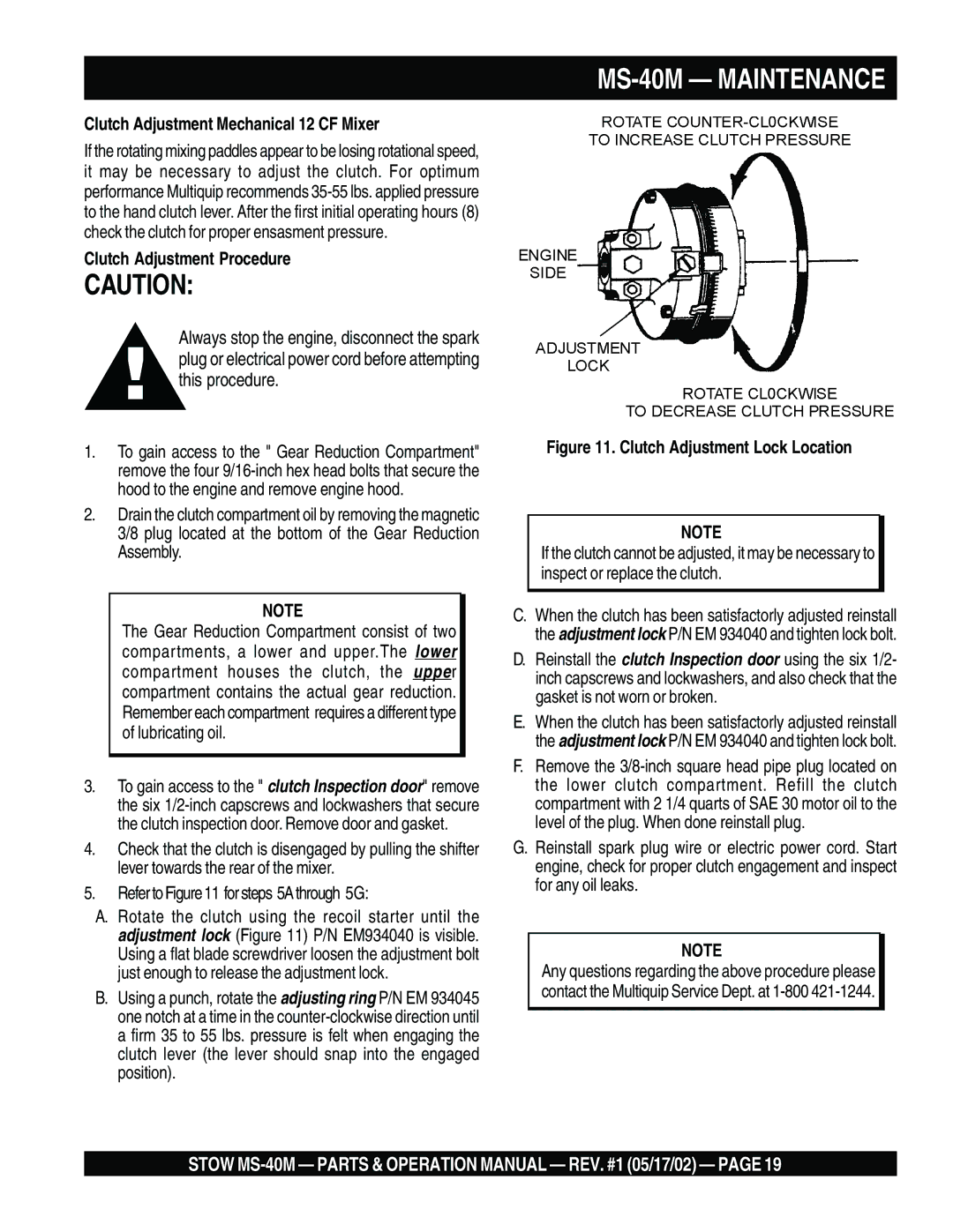
5.Refer to Figure 11 for steps 5A through 5G:
A.Rotate the clutch using the recoil starter until the adjustment lock (Figure 11) P/N EM934040 is visible. Using a flat blade screwdriver loosen the adjustment bolt just enough to release the adjustment lock.
B.Using a punch, rotate the adjusting ring P/N EM 934045 one notch at a time in the
MS-40M — MAINTENANCE
Figure 11. Clutch Adjustment Lock Location
NOTE
If the clutch cannot be adjusted, it may be necessary to inspect or replace the clutch.
C.When the clutch has been satisfactorly adjusted reinstall the adjustment lock P/N EM 934040 and tighten lock bolt.
D.Reinstall the clutch Inspection door using the six 1/2- inch capscrews and lockwashers, and also check that the gasket is not worn or broken.
E.When the clutch has been satisfactorly adjusted reinstall the adjustment lock P/N EM 934040 and tighten lock bolt.
F.Remove the
G.Reinstall spark plug wire or electric power cord. Start engine, check for proper clutch engagement and inspect for any oil leaks.
NOTE
Any questions regarding the above procedure please contact the Multiquip Service Dept. at
STOW