MIXER COMPONENTS
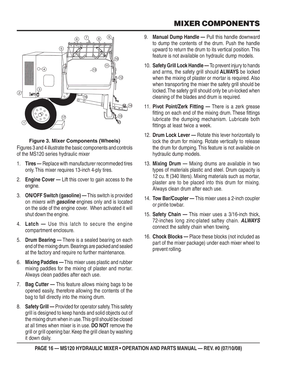
Figure 3. Mixer Components (Wheels)
Figures 3 and 4 illustrate the basic components and controls of the MS120 series hydraulic mixer
1.Tires — Replace with manufacturer recommeded tires only. This mixer requires
2.Engine Cover — Lift this cover to gain access to the engine.
3.ON/OFF Switch (gasoline) — This switch is provided on mixers with gasoline engines only and is located on the side of the engine cover. When activated it will shut down the engine.
4.Latch — Use this latch to secure the engine compartment enclosure.
5.Drum Bearing — There is a sealed bearing on each end of the mixing drum. Bearings are packed and sealed at the factory and require no further maintenance.
6.Mixing Paddles — This mixer uses plastic and rubber mixing paddles for the mixing of plaster and mortar. Always clean paddles after each use.
7.Bag Cutter — This feature allows mixing bags to be opened easily, therefore allowing the contents of the bag to fall directly into the mixing drum.
8.Safety Grill — Provided for operator safety.This safety grill is designed to keep hands and solid objects out of the mixing drum when in use.This grill should be closed at all times when mixer is in use. DO NOT remove the grill or grill opening bar. Keep the grill clean by washing it down daily.
9.Manual Dump Handle — Pull this handle downward to dump the contents of the drum. Push the handle upward to return the drum to its vertical position. This feature is not available on hydraulic dump models.
10.Safety Grill Lock Handle — To prevent injury to hands and arms, the safety grill should ALWAYS be locked when the mixing of plaster or mortar is required. Also when transporting the mixer the safety grill should be locked. The safety grill should only be
11.Pivot Point/Zerk Fitting — There is a zerk grease fitting on each end of the mixing drum. These fittings lubricate the dumping mechanism. Lubricate both fittings at least twice a week.
12.Drum Lock Lever — Rotate this lever horizontally to lock the drum for mixing. Rotate vertically to release the drum for dumping. This feature is not available on hydraulic dump models.
13.Mixing Drum — Mixing drums are available in two types of materials plastic and steel. Drum capacity is 12 cu. ft (340 liters). Mixing materials such as mortar, plaster are to be placed into this drum for mixing. Always clean drum after each use.
14.Tow Bar/Coupler — This mixer uses a
15.Safety Chain — This mixer uses a
16.Chock Blocks — Place these blocks (not included as part of the mixer package) under each mixer wheel to prevent rolling.
PAGE 16 — MS120 HYDRAULIC MIXER • OPERATION AND PARTS MANUAL — REV. #0 (07/10/08)