STUDER INNOTEC |
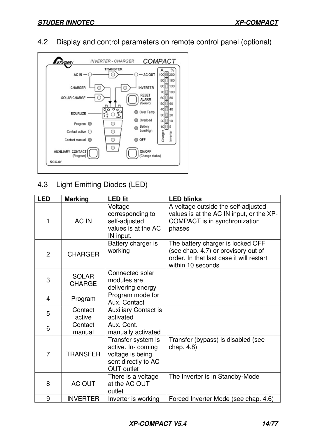
4.2Display and control parameters on remote control panel (optional)
4.3Light Emitting Diodes (LED)
LED | Marking | LED lit | LED blinks |
|
| Voltage | A voltage outside the |
|
| corresponding to | values is at the AC IN input, or the XP- |
1 | AC IN | COMPACT is in synchronization | |
|
| values is at the AC | phases |
|
| IN input. |
|
|
| Battery charger is | The battery charger is locked OFF |
2 | CHARGER | working | (see chap. 4.7) or provisory out of |
| order. In that last case it will restart | ||
|
|
| |
|
|
| within 10 seconds |
| SOLAR | Connected solar |
|
3 | modules are |
| |
CHARGE |
| ||
| delivering energy |
| |
|
|
| |
4 | Program | Program mode for |
|
Aux. Contact |
| ||
|
|
| |
5 | Contact | Auxiliary Contact is |
|
active | activated |
| |
|
| ||
6 | Contact | Aux. Cont. |
|
manual | manually activated |
| |
|
| ||
|
| Transfer system is | Transfer (bypass) is disabled (see |
|
| active. In- coming | chap. 4.8) |
7 | TRANSFER | voltage is being |
|
|
| sent directly to AC |
|
|
| OUT outlet |
|
|
| There is a voltage | The Inverter is in |
8 | AC OUT | at the AC OUT |
|
|
| outlet |
|
9 | INVERTER | Inverter is working | Forced Inverter Mode (see chap. 4.6) |
| 14/77 |