STUDER INNOTEC |
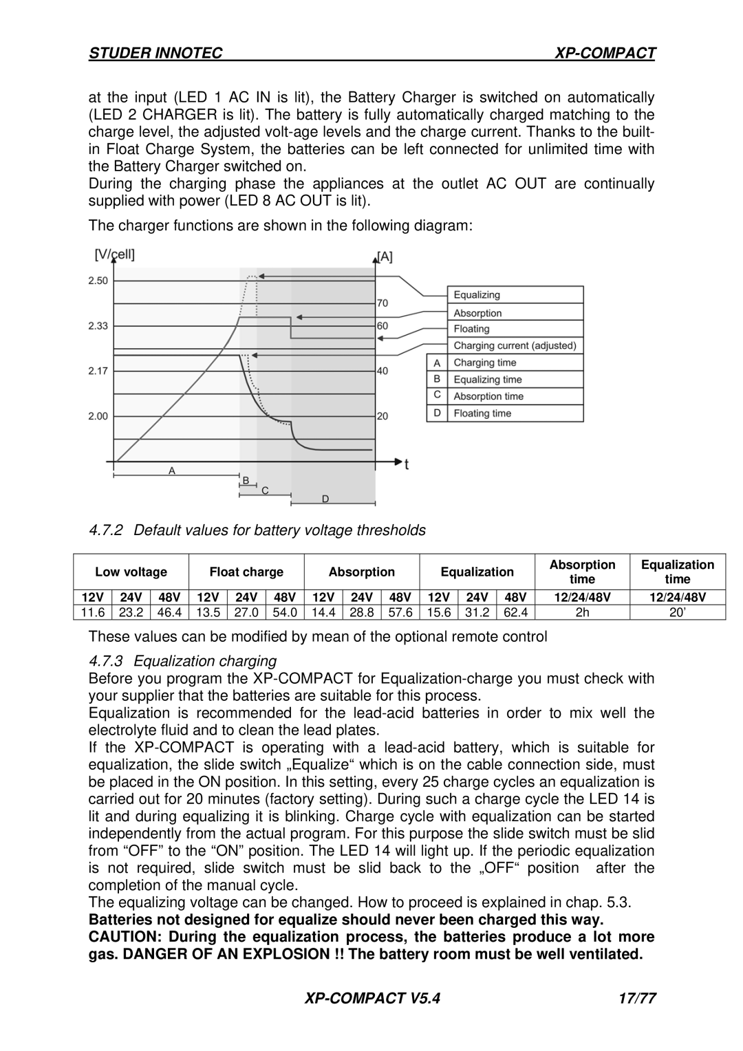
at the input (LED 1 AC IN is lit), the Battery Charger is switched on automatically (LED 2 CHARGER is lit). The battery is fully automatically charged matching to the charge level, the adjusted
During the charging phase the appliances at the outlet AC OUT are continually supplied with power (LED 8 AC OUT is lit).
The charger functions are shown in the following diagram:
4.7.2 Default values for battery voltage thresholds
Low voltage | Float charge | Absorption | Equalization | Absorption | Equalization | |||||||||
time | time | |||||||||||||
|
|
|
|
|
|
|
|
|
|
|
| |||
|
|
|
|
|
|
|
|
|
|
|
|
|
| |
12V | 24V | 48V | 12V | 24V | 48V | 12V | 24V | 48V | 12V | 24V | 48V | 12/24/48V | 12/24/48V | |
11.6 | 23.2 | 46.4 | 13.5 | 27.0 | 54.0 | 14.4 | 28.8 | 57.6 | 15.6 | 31.2 | 62.4 | 2h | 20’ | |
These values can be modified by mean of the optional remote control
4.7.3 Equalization charging
Before you program the
Equalization is recommended for the
If the
The equalizing voltage can be changed. How to proceed is explained in chap. 5.3.
Batteries not designed for equalize should never been charged this way. CAUTION: During the equalization process, the batteries produce a lot more gas. DANGER OF AN EXPLOSION !! The battery room must be well ventilated.
| 17/77 |
