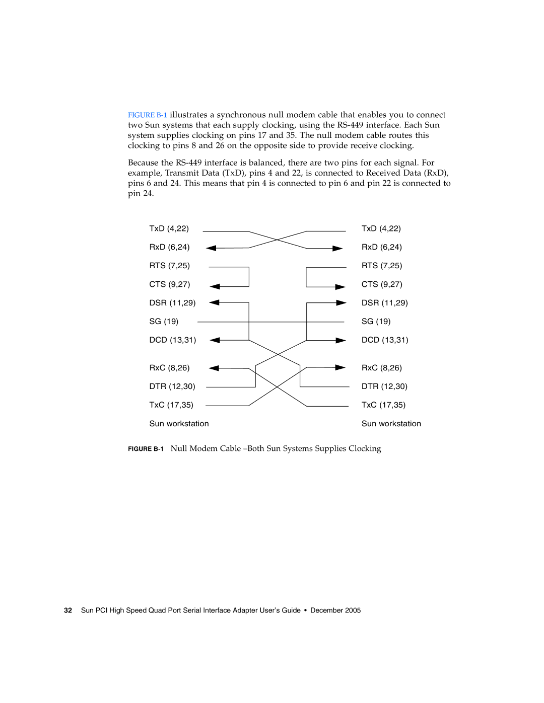
FIGURE B-1 illustrates a synchronous null modem cable that enables you to connect two Sun systems that each supply clocking, using the RS-449 interface. Each Sun system supplies clocking on pins 17 and 35. The null modem cable routes this clocking to pins 8 and 26 on the opposite side to provide receive clocking.
Because the RS-449 interface is balanced, there are two pins for each signal. For example, Transmit Data (TxD), pins 4 and 22, is connected to Received Data (RxD), pins 6 and 24. This means that pin 4 is connected to pin 6 and pin 22 is connected to pin 24.
TxD (4,22) | TxD (4,22) |
RxD (6,24) | RxD (6,24) |
RTS (7,25)
RTS (7,25)
CTS (9,27)
CTS (9,27)
DSR (11,29)
DSR (11,29)
SG (19)
SG (19)
DCD (13,31)
DCD (13,31)
RxC (8,26) | RxC (8,26) |
DTR (12,30) | DTR (12,30) |
TxC (17,35) | TxC (17,35) |
Sun workstation | Sun workstation |
FIGURE B-1 Null Modem Cable –Both Sun Systems Supplies Clocking
32 Sun PCI High Speed Quad Port Serial Interface Adapter User’s Guide • December 2005