5014C-T specifications
The Supermicro 5014C-T is a powerful and versatile server designed for applications that demand high performance, reliability, and scalability. Leveraging the latest technologies, the 5014C-T is engineered to provide an exceptional computing experience in data centers, virtualization environments, and enterprise applications.One of the standout features of the Supermicro 5014C-T is its support for the latest Intel processors. This model is equipped with the Intel Xeon Scalable family of processors, which deliver unparalleled processing power and efficiency. The architecture enhances performance per watt, thus optimizing power consumption and reducing operational costs.
Another significant characteristic of the 5014C-T is its robust memory capacity. The server supports up to 1TB of DDR4 ECC memory across 16 DIMM slots, offering substantial bandwidth and memory capacity to handle memory-intensive applications. This is particularly advantageous for environments running large databases, in-memory computing, or complex analytical workloads.
Storage flexibility is also a key feature of the 5014C-T. The system supports multiple storage options including SATA, SAS, and NVMe drives, enabling organizations to configure their storage solutions according to their specific performance and capacity requirements. With support for up to 8 hot-swappable 3.5-inch HDDs and an optional NVMe SSD adapter, users can achieve rapid data access and exceptional I/O performance.
Networking is critical for modern applications, and the Supermicro 5014C-T does not disappoint. It includes integrated dual 10G Ethernet ports, which provide high-speed connectivity for data transfers and communications between servers. Additionally, the server is equipped with an advanced management system, allowing for remote monitoring and management without requiring physical access to the hardware.
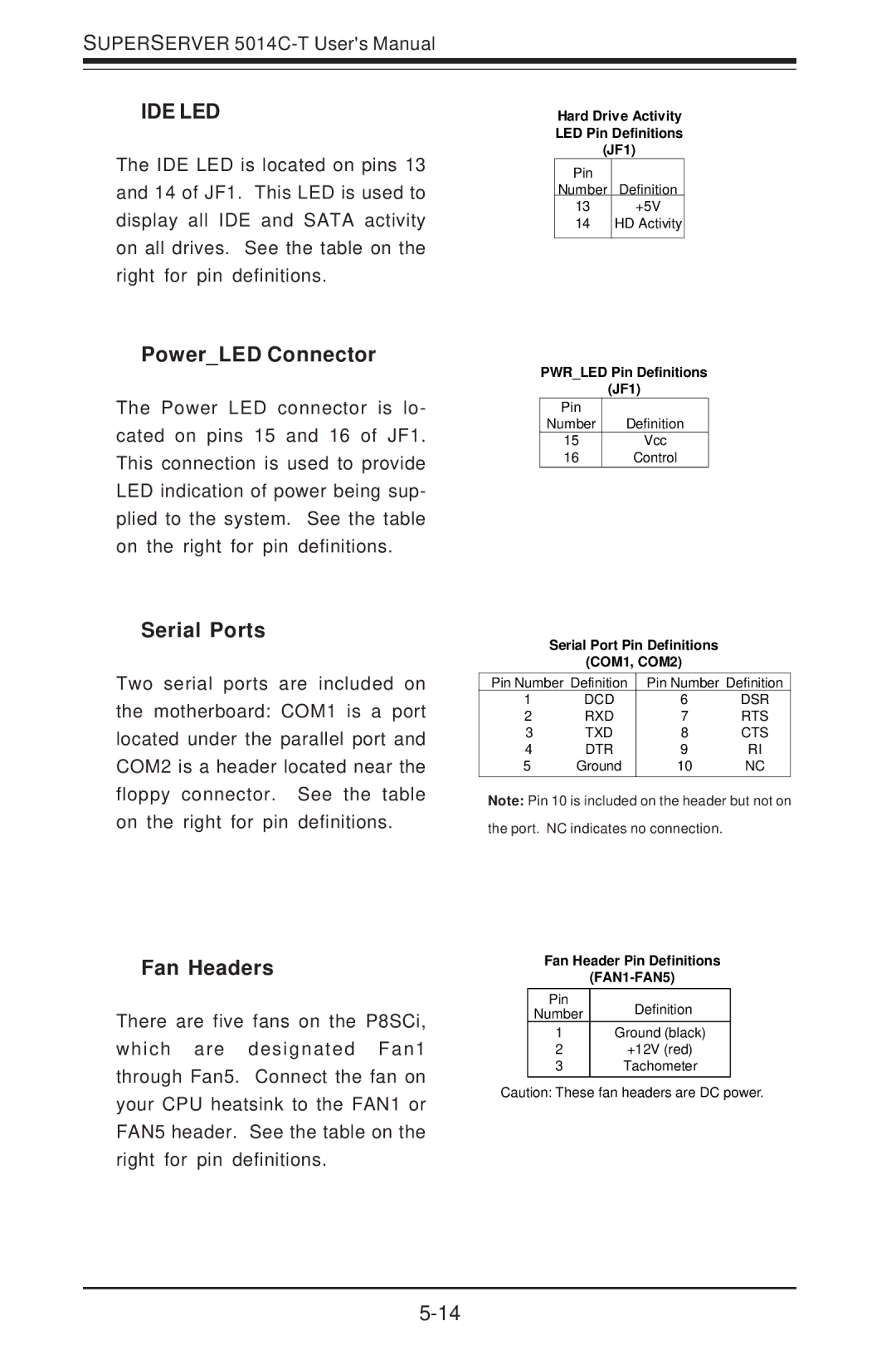
Supermicro's extensive cooling solutions ensure efficient thermal management, allowing the 5014C-T to operate optimally even under heavy loads. This emphasis on cooling helps maintain the longevity of the components, thereby enhancing overall server reliability.
In summary, the Supermicro 5014C-T is designed for high-performance computing scenarios where efficiency, speed, and reliability are paramount. Combining advanced Intel processors, significant memory capacity, flexible storage options, and superior networking capabilities, it stands out as a formidable option for modern data-driven organizations seeking robust server solutions.

