X7DB8/X7DBE User's Manual

Power Fault (PWR Supply Failure)

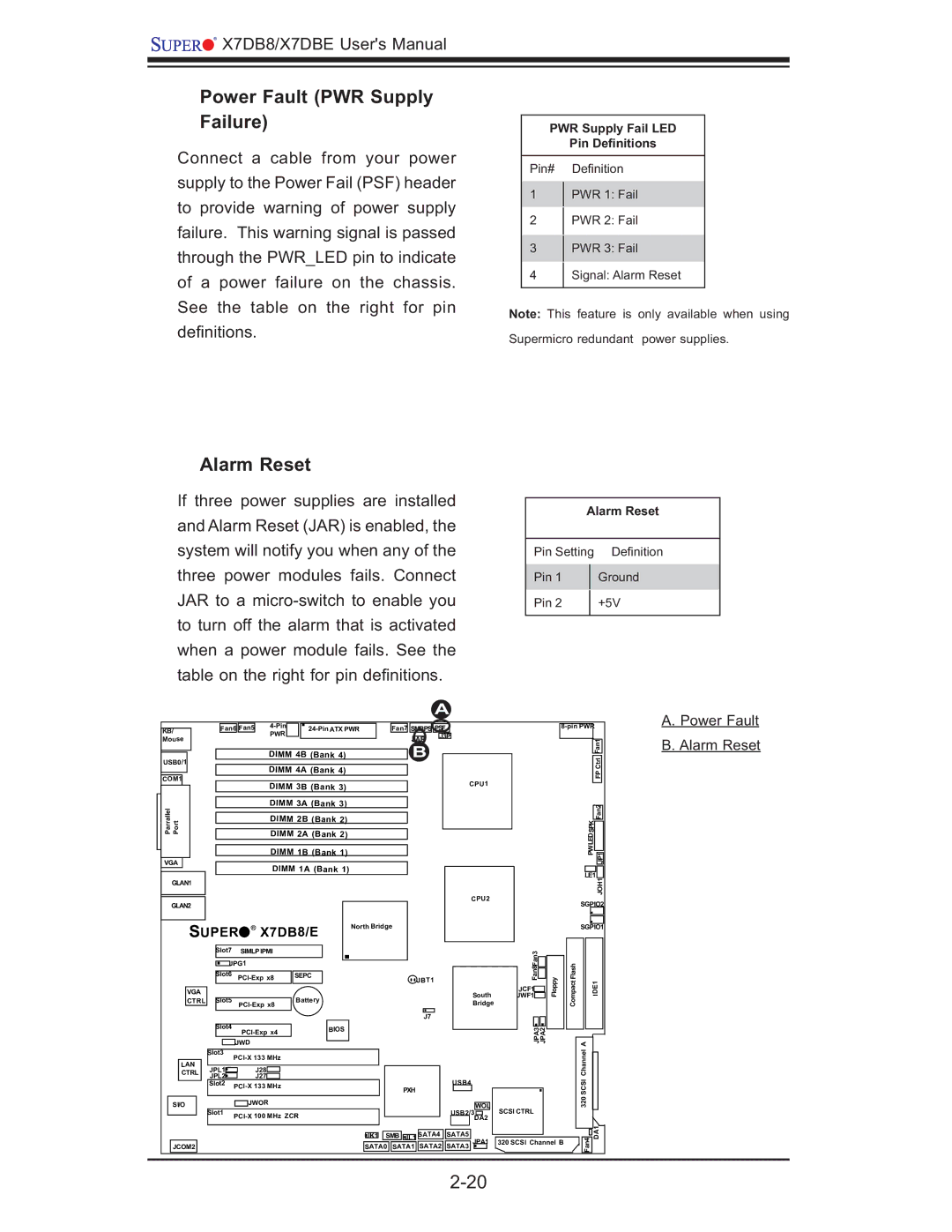
Connect a cable from your power supply to the Power Fail (PSF) header to provide warning of power supply failure. This warning signal is passed through the PWR_LED pin to indicate of a power failure on the chassis. See the table on the right for pin defi nitions.

PWR Supply Fail LED

Pin Definitions

Pin# Defi nition

1PWR 1: Fail

2 PWR 2: Fail

3PWR 3: Fail

4Signal: Alarm Reset

Note: This feature is only available when using Supermicro redundant power supplies.

Alarm Reset

If three power supplies are installed and Alarm Reset (JAR) is enabled, the system will notify you when any of the three power modules fails. Connect JAR to a micro-switch to enable you to turn off the alarm that is activated when a power module fails. See the table on the right for pin defi nitions.

Alarm Reset

Pin Setting

Defi nition

Pin 1


Ground

Pin 2


+5V


A


A. Power Fault

KB/

Fan6

Fan5

4-Pin

24-Pin ATX PWR


Fan7

SMBPS PSF


8-pin PWR


PWR


Mouse


JAR

J3P


Fan1

B. Alarm Reset


DIMM 4B (Bank 4)


B


USB0/1


Ctrl


DIMM 4A (Bank 4)


COM1


FP


CPU1


DIMM 3B (Bank 3)


ParrallelPortJLAN1


DIMM 3A (Bank 3)


LEDSPK

Fan2


DIMM 2B (Bank 2)


DIMM 2A (Bank 2)


DIMM 1B (Bank 1)


PW

JP1


VGA


DIMM 1A (Bank 1)


LE1


GLAN1


JOH1


GLAN2


CPU2


SGPIO2


SUPER

X7DB8/E

North Bridge


SGPIO1


Slot7


SIMLP IPMI


Fan8Fan3


PCI-Exp x8

SEPC


JBT1


JPG1


Floppy


CompactFlash


Slot6


PCI-Exp x8


VGA


South

JCF1


IDE1


JWF1


CTRL

Slot5


Battery


Bridge


J7


Slot4


PCI-Exp x4

BIOS


JPA3 JPA2


CTRL


JWD


A


Slot3

PCI-X 133 MHz


Channel


LAN


JPL1


J28


JPL2


J27


USB4


SCSI


Slot2

PCI-X 133 MHz


PXH


320


SI/O


JWOR


WOL


Slot1

PCI-X 100 MHz ZCR


USB2/3

SCSI CTRL


DA2


Fan4 DA1


JK1

SMB

JL1

SATA4

SATA5


JPA1

320 SCSI Channel B


JCOM2


SATA0

SATA1 SATA2 SATA3


2-20


Page 40
Image 40
SUPER MICRO Computer X7DBE, X7DB8 user manual Power Fault PWR Supply Failure, Alarm Reset

X7DB8, X7DBE specifications

Super Micro Computer, a global leader in high-performance server and storage solutions, has developed a range of advanced server motherboards, among which the X7DBE and X7DB8 stand out for their robust performance and versatility. Designed for data-intensive applications, these motherboards cater to various markets, including cloud computing, enterprise data centers, and video surveillance.

The X7DBE motherboards are built on the Intel 5000 series chipset and support dual Intel Xeon processors, which provide exceptional processing power for demanding applications. With a maximum memory capacity of 64GB, these motherboards cater to memory-intensive workloads, making them ideal for virtualization and database applications. The X7DBE supports both ECC (Error-Correcting Code) and non-ECC memory, enhancing system reliability and data integrity.

In terms of storage, the X7DBE is equipped with multiple 3.5-inch SATA hard drive bays that allow for substantial data storage capabilities. Additionally, it includes integrated RAID support, enabling users to configure their storage environment for optimal performance and redundancy. The advanced thermal management technology ensures efficient cooling, promoting system stability and longevity even under heavy workloads.

The X7DB8, on the other hand, takes performance a notch higher by providing support for the latest Intel processors and offering enhanced features geared toward high-performance computing. Like the X7DBE, it supports dual processors but extends capability for larger memory configurations, allowing up to 128GB of DDR2 memory. This flexibility makes the X7DB8 an excellent choice for mission-critical applications requiring immense processing power.

Both motherboards come equipped with multiple PCI Express slots, enabling the installation of add-on cards for tasks such as enhanced graphics, additional network interfaces, or dedicated storage controllers, thus providing scalability to meet the growing demands of modern applications. Network connectivity is robust, with several Gigabit Ethernet ports ensuring high-speed data transfer.

In conclusion, Super Micro's X7DBE and X7DB8 motherboards exemplify the perfect blend of performance, scalability, and reliability. With their support for advanced technologies and their ability to handle high workloads, they are ideal solutions for businesses seeking to optimize their server infrastructure. As technology continues to evolve, these motherboards remain pertinent, providing a solid foundation for various applications and future advancements.