Firebox Framing
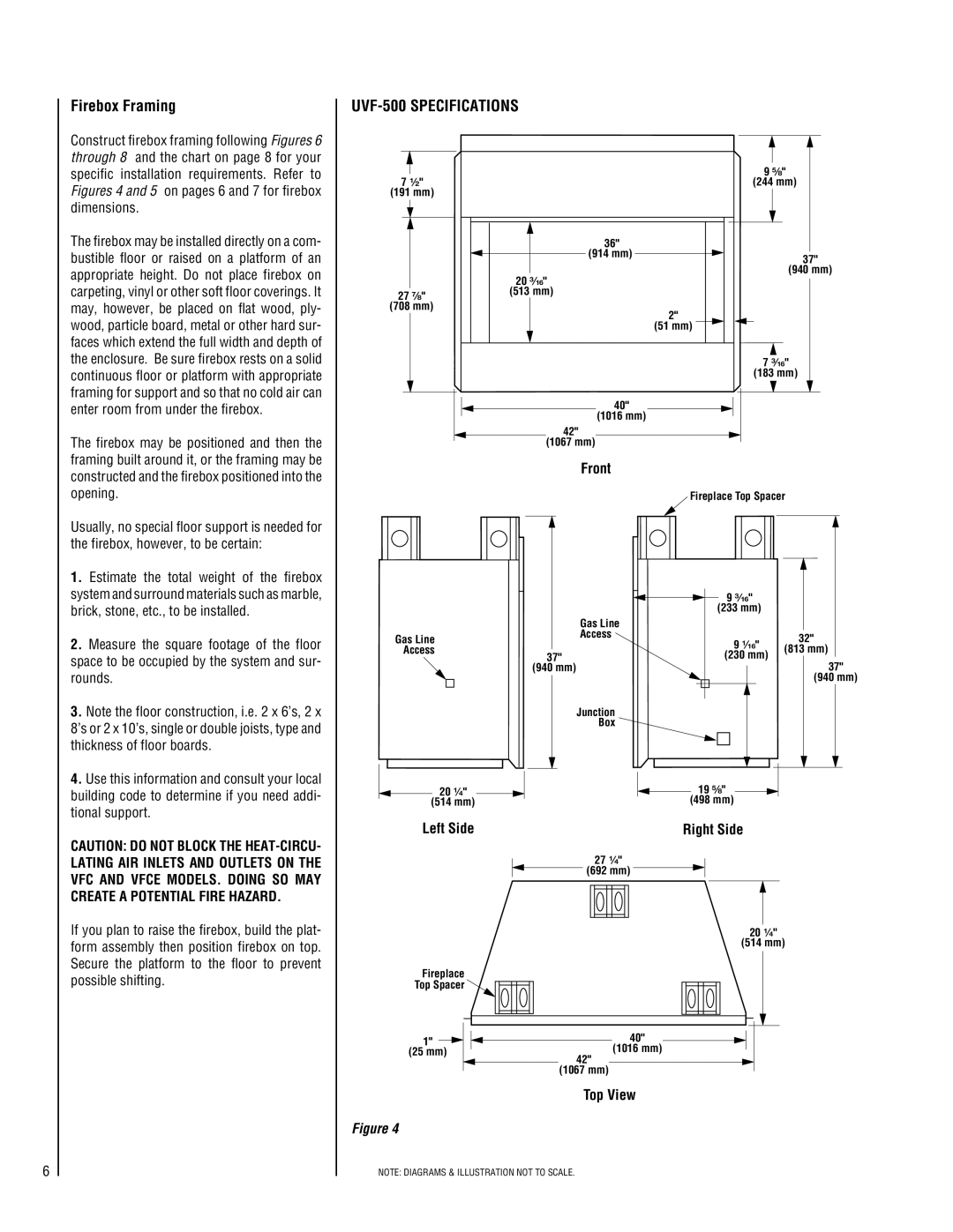
Construct firebox framing following Figures 6 through 8 and the chart on page 8 for your specific installation requirements. Refer to Figures 4 and 5 on pages 6 and 7 for firebox dimensions.
The firebox may be installed directly on a com- bustible floor or raised on a platform of an appropriate height. Do not place firebox on carpeting, vinyl or other soft floor coverings. It may, however, be placed on flat wood, ply- wood, particle board, metal or other hard sur- faces which extend the full width and depth of the enclosure. Be sure firebox rests on a solid continuous floor or platform with appropriate framing for support and so that no cold air can enter room from under the firebox.
The firebox may be positioned and then the framing built around it, or the framing may be constructed and the firebox positioned into the opening.
Usually, no special floor support is needed for the firebox, however, to be certain:
1. Estimate the total weight of the firebox |
system and surround materials such as marble, |
brick, stone, etc., to be installed. |
2. Measure the square footage of the floor |
space to be occupied by the system and sur- |
rounds. |
3. Note the floor construction, i.e. 2 x 6’s, 2 x |
8’s or 2 x 10’s, single or double joists, type and |
thickness of floor boards. |
UVF-500 SPECIFICATIONS
9 ⁵⁄₈"
7 ¹⁄₂"(244 mm)
(191 mm)
36"
![]() (914 mm)
(914 mm) ![]() 37" (940 mm)
37" (940 mm)
| 20 ³⁄₁₆" |
27 ⁷⁄₈" | (513 mm) |
(708 mm) |
|
2"
(51 mm)
7 ³⁄₁₆"
(183 mm)
40" (1016 mm)
42"
(1067 mm)
Front
Fireplace Top Spacer
|
|
|
|
|
|
|
|
|
|
|
| 9 ³⁄₁₆" |
|
| |
|
|
|
|
|
|
|
|
|
|
|
|
|
| ||
|
|
|
|
|
|
|
|
|
|
|
|
|
| ||
|
|
|
|
|
|
|
|
|
|
| (233 mm) |
|
| ||
|
|
|
| Gas Line |
|
|
|
|
|
|
| ||||
Gas Line |
|
|
| Access |
|
|
| 9 ¹⁄₁₆" | 32" |
| |||||
Access |
|
|
|
|
|
|
|
|
|
|
| (813 mm) |
| ||
37" |
|
|
|
|
|
|
|
| (230 mm) |
| |||||
|
|
|
|
|
|
|
|
| 37" | ||||||
| (940 mm) |
|
|
|
|
|
|
|
|
|
| ||||
|
|
|
|
|
|
|
|
|
|
|
|
|
| (940 mm) | |
|
|
|
|
|
|
|
|
|
|
|
|
|
| ||
|
|
|
| Junction |
|
|
|
|
|
| |||||
|
|
|
| Box |
|
|
|
|
|
| |||||
|
|
|
|
|
|
|
|
|
|
|
|
|
|
|
|
|
|
|
|
|
|
|
|
|
|
|
|
|
|
|
|
4. Use this information and consult your local |
building code to determine if you need addi- |
tional support. |
CAUTION: DO NOT BLOCK THE
If you plan to raise the firebox, build the plat- form assembly then position firebox on top. Secure the platform to the floor to prevent possible shifting.
20 ¹⁄₄"
(514 mm)
Left Side
Fireplace
Top Spacer ![]()
1" ![]() (25 mm)
(25 mm)
![]() 19 ⁵⁄₈"
19 ⁵⁄₈" ![]() (498 mm)
(498 mm)
Right Side
27¹⁄₄"
(692 mm)
20 ¹⁄₄"
(514 mm)
40" (1016 mm)
42" (1067 mm)
Top View
6
Figure 4
NOTE: DIAGRAMS & ILLUSTRATION NOT TO SCALE.