Operating Manual

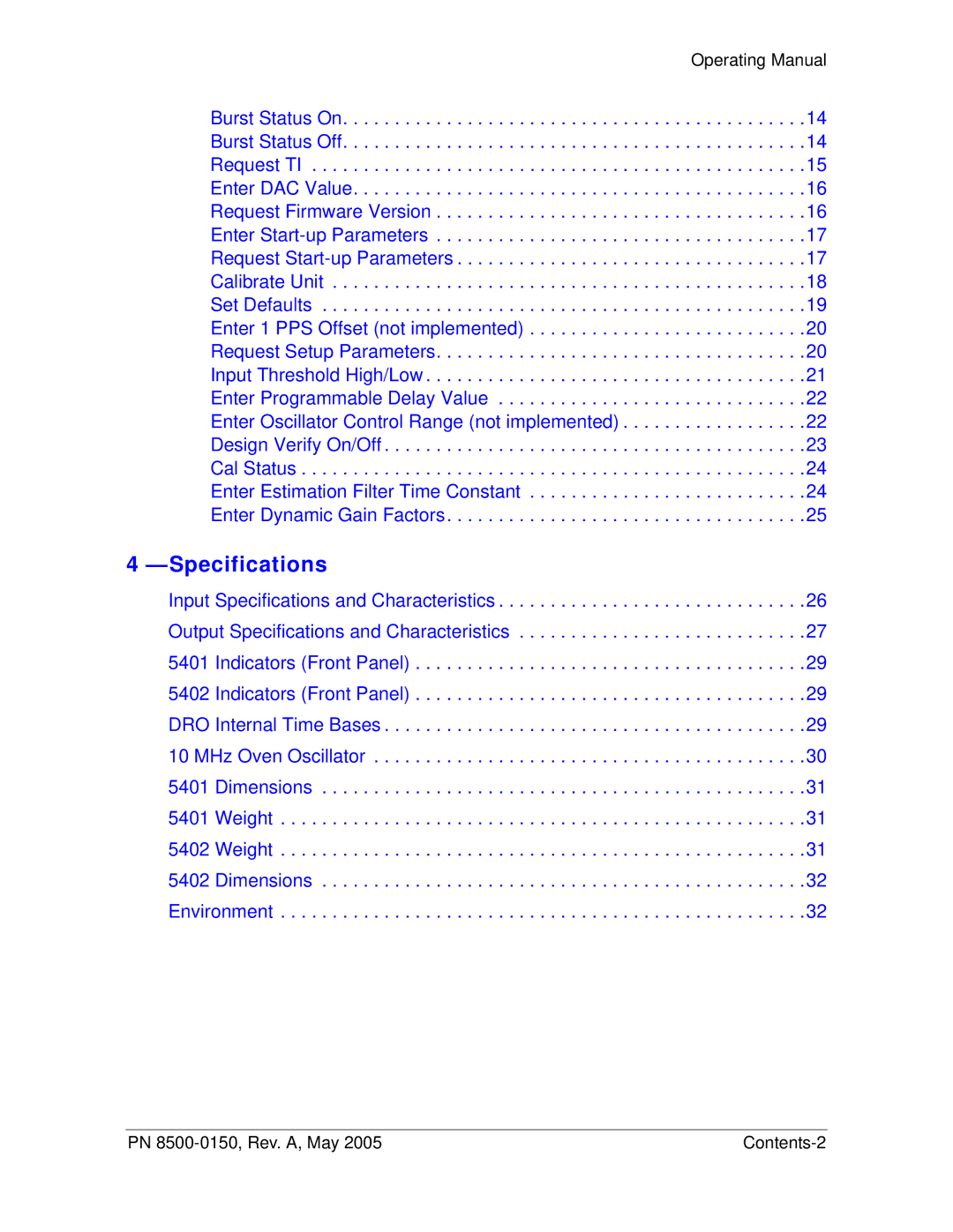
Burst Status On. . . . . . . . . . . . . . . . . . . . . . . . . . . . . . . . . . . . . . . . . . . . .14 Burst Status Off. . . . . . . . . . . . . . . . . . . . . . . . . . . . . . . . . . . . . . . . . . . . .14 Request TI . . . . . . . . . . . . . . . . . . . . . . . . . . . . . . . . . . . . . . . . . . . . . . . .15 Enter DAC Value. . . . . . . . . . . . . . . . . . . . . . . . . . . . . . . . . . . . . . . . . . . .16 Request Firmware Version . . . . . . . . . . . . . . . . . . . . . . . . . . . . . . . . . . . .16 Enter Start-up Parameters . . . . . . . . . . . . . . . . . . . . . . . . . . . . . . . . . . . .17 Request Start-up Parameters . . . . . . . . . . . . . . . . . . . . . . . . . . . . . . . . . .17 Calibrate Unit . . . . . . . . . . . . . . . . . . . . . . . . . . . . . . . . . . . . . . . . . . . . . .18 Set Defaults . . . . . . . . . . . . . . . . . . . . . . . . . . . . . . . . . . . . . . . . . . . . . . .19 Enter 1 PPS Offset (not implemented) . . . . . . . . . . . . . . . . . . . . . . . . . . .20 Request Setup Parameters. . . . . . . . . . . . . . . . . . . . . . . . . . . . . . . . . . . .20 Input Threshold High/Low . . . . . . . . . . . . . . . . . . . . . . . . . . . . . . . . . . . . .21 Enter Programmable Delay Value . . . . . . . . . . . . . . . . . . . . . . . . . . . . . .22 Enter Oscillator Control Range (not implemented) . . . . . . . . . . . . . . . . . .22 Design Verify On/Off . . . . . . . . . . . . . . . . . . . . . . . . . . . . . . . . . . . . . . . . .23 Cal Status . . . . . . . . . . . . . . . . . . . . . . . . . . . . . . . . . . . . . . . . . . . . . . . . .24 Enter Estimation Filter Time Constant . . . . . . . . . . . . . . . . . . . . . . . . . . .24 Enter Dynamic Gain Factors. . . . . . . . . . . . . . . . . . . . . . . . . . . . . . . . . . .25

4 —Specifications

Input Specifications and Characteristics . . . . . . . . . . . . . . . . . . . . . . . . . . . . . .26 Output Specifications and Characteristics . . . . . . . . . . . . . . . . . . . . . . . . . . . .27

5401 Indicators (Front Panel) . . . . . . . . . . . . . . . . . . . . . . . . . . . . . . . . . . . . . .29

5402 Indicators (Front Panel) . . . . . . . . . . . . . . . . . . . . . . . . . . . . . . . . . . . . . .29

DRO Internal Time Bases . . . . . . . . . . . . . . . . . . . . . . . . . . . . . . . . . . . . . . . . .29

10 MHz Oven Oscillator . . . . . . . . . . . . . . . . . . . . . . . . . . . . . . . . . . . . . . . . . .30

5401 Dimensions . . . . . . . . . . . . . . . . . . . . . . . . . . . . . . . . . . . . . . . . . . . . . . .31

5401 Weight . . . . . . . . . . . . . . . . . . . . . . . . . . . . . . . . . . . . . . . . . . . . . . . . . . .31

5402 Weight . . . . . . . . . . . . . . . . . . . . . . . . . . . . . . . . . . . . . . . . . . . . . . . . . . .31

5402 Dimensions . . . . . . . . . . . . . . . . . . . . . . . . . . . . . . . . . . . . . . . . . . . . . . .32

Environment . . . . . . . . . . . . . . . . . . . . . . . . . . . . . . . . . . . . . . . . . . . . . . . . . . .32

PN 8500-0150, Rev. A, May 2005

Contents-2

Page 8
Image 8
Symmetricom 5402, 5401 manual Specifications, Operating Manual

5401, 5402 specifications

The Symmetricom 5402 and 5401 are highly regarded timing and synchronization solutions designed for telecommunications and data networking applications. These devices are part of the renowned line of precision timekeeping products developed by Symmetricom, which is now known as Microchip Technology.

The Symmetricom 5402 offers advanced capabilities, including GPS and precision time protocol (PTP) synchronization. It provides an accurate and stable time reference, crucial for industries that require precise timing to ensure system integrity and communication efficiency. The 5402 supports various synchronization protocols including IEEE 1588v2, ensuring interoperability with existing systems. This allows organizations to implement cutting-edge technologies while maintaining compatibility with older infrastructure.

On the other hand, the Symmetricom 5401 serves as a more compact and economical option tailored for specific applications where full GPS capabilities may not be necessary. This unit simplifies the synchronization process while still offering reliable performance. The 5401 provides multiple outputs including T1/E1 and 10 MHz, making it versatile for different network configurations.

Both models incorporate advanced oscillator technology that ensures accuracy and stability. They have a temperature-compensated crystal oscillator (TCXO) or optional oven-controlled crystal oscillator (OCXO) that provides superior frequency stability across a wide range of operating conditions. These devices also feature high-performance phase-locked loops (PLLs), which enhance their ability to maintain synchronization over time and under varying operational environments.

Additional features include robust network management capabilities, allowing for real-time monitoring and diagnostics through a user-friendly interface. The devices are equipped with multiple input/output ports that facilitate seamless integration into existing network architectures. The Symmetricom 5402 and 5401 support both local and remote management, enabling network administrators to maintain optimal synchronization performance.

In summary, the Symmetricom 5402 and 5401 deliver reliable, high-precision timing solutions designed to meet the demands of modern telecommunications infrastructures. With their advanced synchronization technologies, versatile connectivity options, and robust performance characteristics, these devices are essential components for ensuring accurate timekeeping in any network. Whether organizations choose the feature-rich 5402 or the cost-effective 5401, they can be confident in the reliability and precision these products deliver.