
1400 specifications
The System Sensor 1400 series is an advanced line of smoke detectors designed to enhance safety in commercial and industrial settings. Known for its reliability and precision, the 1400 series employs cutting-edge technologies to ensure early detection of smoke and fire, thus providing crucial time for evacuation and response.One of the main features of the System Sensor 1400 is its dual-sensor technology, which combines both photoelectric and ionization detection methods. This dual approach allows the detector to identify a wide range of smoke particles generated from various types of fires, from fast-flaming fires to smoldering ones. This versatility significantly reduces the chances of false alarms while maintaining a high level of sensitivity.
Another key technological advancement in the 1400 series is its built-in communication capabilities. The detectors can be integrated into larger fire alarm systems, allowing for remote monitoring and real-time alerts. This integration is facilitated by the use of an advanced communication protocol that enables quick data transmission and reduces response times in emergencies.
The System Sensor 1400 series also features a robust design that ensures durability and reliability. Constructed from high-quality materials, these detectors are resistant to environmental factors such as humidity and temperature fluctuations. This makes them suitable for a variety of settings, including warehouses, manufacturing plants, and commercial buildings.
In addition, the 1400 series incorporates a user-friendly interface that simplifies installation and maintenance. The detectors are equipped with LED indicators that provide visual alerts for operational status, including power, alarm, and trouble signals. This allows maintenance personnel to quickly assess the detector’s functionality and perform necessary checks or replacements.
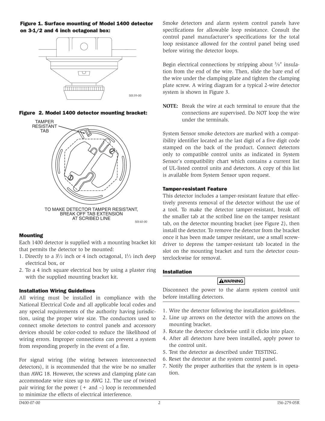
Ease of installation is further enhanced by the use of a universal mounting bracket, which simplifies the setup process and reduces downtime. The series is also designed to accommodate various power options, including battery backup, ensuring continued operation even during power outages.
In conclusion, the System Sensor 1400 series stands out as a premier choice for smoke detection in commercial and industrial applications. Its combination of dual-sensor technology, robust design, seamless integration capabilities, and user-friendly features makes it a reliable solution for enhancing fire safety and protection in any environment.