Mounting
Each i3 Series detector is supplied with a mounting base that can be mounted:
1.To a single gang box, or
2.To a
3.To a
4.Direct mount or to ceiling using drywall fasteners (Figure 2).
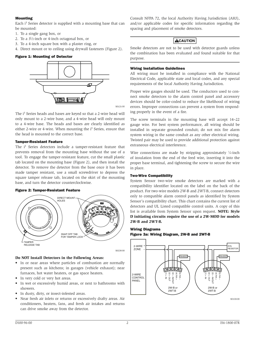
Figure 1: Mounting of Detector
The i3 Series heads and bases are keyed so that a
Tamper-Resistant Feature
The i3 Series detectors include a
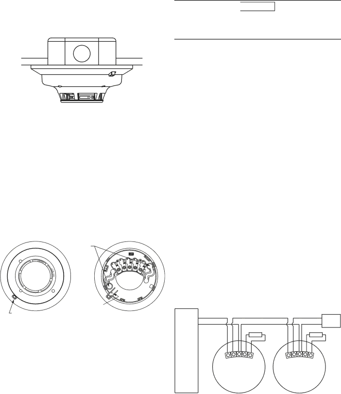
Figure 2: Tamper-Resistant Feature
DIRECT MOUNT
HOLES
SNAP OFF TAB
FOR TAMPER LOCK
Consult NFPA 72, the local Authority Having Jurisdiction (AHJ), and/or applicable codes for specific information regarding the spacing and placement of smoke detectors.
![]()
![]() CAUTION
CAUTION
Smoke detectors are not to be used with detector guards unless the combination has been evaluated and found suitable for that purpose.
Wiring Installation Guidelines
All wiring must be installed in compliance with the National Electrical Code, applicable state and local codes, and any special requirements of the local Authority Having Jurisdiction.
Proper wire gauges should be used. The conductors used to con- nect smoke detectors to the alarm control panel and accessory devices should be
The screw terminals in the mounting base will accept
Wire connections are made by stripping approximately
Two-Wire Compatibility
System Sensor
D initiating circuits require the use of a
Wiring Diagrams
Figure 3a: Wiring Diagram, 2W-B and 2WT-B
TAMPER
RELEASE TAB
Do NOT Install Detectors in the Following Areas:
• In or near areas where particles of combustion are normally |
present such as kitchens; in garages (vehicle exhaust); near |
furnaces, hot water heaters, or gas space heaters. |
• In very cold or very hot areas. |
• In wet or excessively humid areas, or next to bathrooms with |
showers. |
• In dusty, dirty, or |
2-WIRE + ZONE –
2-WIRE CONTROL PANEL
RA400Z
(5) RA – (4) RA + (3) – IN/OUT (2) + OUT (1) + IN
EOL
RESISTOR
RA400Z
(5) RA – (4) RA + (3) – IN/OUT (2) + OUT (1) + IN
• Near fresh air inlets or returns or excessively drafty areas. Air |
conditioners, heaters, fans, and fresh air intakes and returns |
can drive smoke away from the detector. |
2 |