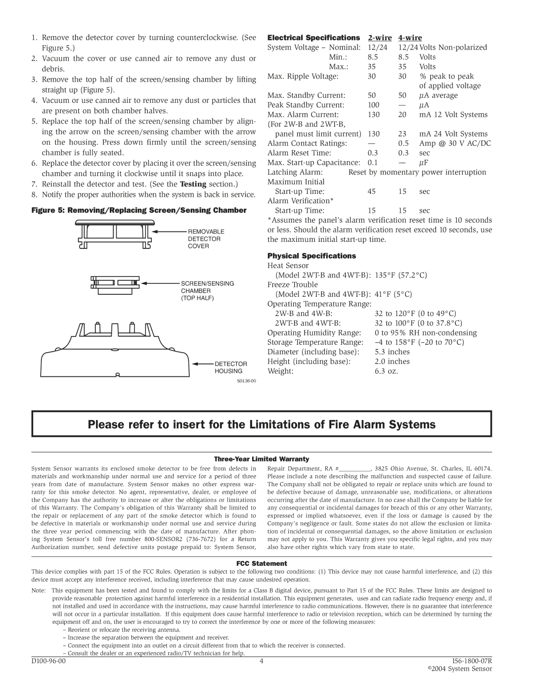
1.Remove the detector cover by turning counterclockwise. (See Figure 5.)
2.Vacuum the cover or use canned air to remove any dust or debris.
3.Remove the top half of the screen/sensing chamber by lifting straight up (Figure 5).
4.Vacuum or use canned air to remove any dust or particles that are present on both chamber halves.
5.Replace the top half of the screen/sensing chamber by align- ing the arrow on the screen/sensing chamber with the arrow on the housing. Press down firmly until the screen/sensing chamber is fully seated.
6.Replace the detector cover by placing it over the screen/sensing chamber and turning it clockwise until it snaps into place.
7.Reinstall the detector and test. (See the Testing section.)
8.Notify the proper authorities when the system is back in service.
Figure 5: Removing/Replacing Screen/Sensing Chamber
![]() REMOVABLE
REMOVABLE
DETECTOR
COVER
![]() SCREEN/SENSING CHAMBER
SCREEN/SENSING CHAMBER
(TOP HALF)
![]() DETECTOR
DETECTOR
HOUSING
Electrical Specifications |
| |||
System Voltage – Nominal: | 12/24 | 12/24Volts | ||
Min.: |
| 8.5 | 8.5 | Volts |
Max.: |
| 35 | 35 | Volts |
Max. Ripple Voltage: |
| 30 | 30 | % peak to peak |
|
|
|
| of applied voltage |
Max. Standby Current: |
| 50 | 50 | µA average |
Peak Standby Current: |
| 100 | — | µA |
Max. Alarm Current: |
| 130 | 20 | mA 12 Volt Systems |
(For |
|
|
|
|
panel must limit current) | 130 | 23 | mA 24 Volt Systems | |
Alarm Contact Ratings: |
| — | 0.5 | Amp @ 30 V AC/DC |
Alarm Reset Time: |
| 0.3 | 0.3 | sec |
Max. | 0.1 | — | µF | |
Latching Alarm: | Reset by momentary power interruption | |||
Maximum Initial |
|
|
|
|
| 45 | 15 | sec | |
Alarm Verification* |
|
|
|
|
| 15 | 15 | sec | |
*Assumes the panel’s alarm verification reset time is 10 seconds or less. Should the alarm verification reset exceed 10 seconds, use the maximum initial
Physical Specifications
Heat Sensor
(Model
(Model
Operating Humidity Range:
Storage Temperature Range: Diameter (including base): Height (including base):
Weight:
Please refer to insert for the Limitations of Fire Alarm Systems
Three-Year Limited Warranty
System Sensor warrants its enclosed smoke detector to be free from defects in materials and workmanship under normal use and service for a period of three years from date of manufacture. System Sensor makes no other express war- ranty for this smoke detector. No agent, representative, dealer, or employee of the Company has the authority to increase or alter the obligations or limitations of this Warranty. The Company’s obligation of this Warranty shall be limited to the repair or replacement of any part of the smoke detector which is found to be defective in materials or workmanship under normal use and service during the three year period commencing with the date of manufacture. After phon- ing System Sensor’s toll free number
Repair Department, RA #__________, 3825 Ohio Avenue, St. Charles, IL 60174.
Please include a note describing the malfunction and suspected cause of failure. The Company shall not be obligated to repair or replace units which are found to be defective because of damage, unreasonable use, modifications, or alterations occurring after the date of manufacture. In no case shall the Company be liable for any consequential or incidental damages for breach of this or any other Warranty, expressed or implied whatsoever, even if the loss or damage is caused by the Company’s negligence or fault. Some states do not allow the exclusion or limita- tion of incidental or consequential damages, so the above limitation or exclusion may not apply to you. This Warranty gives you specific legal rights, and you may also have other rights which vary from state to state.
FCC Statement
This device complies with part 15 of the FCC Rules. Operation is subject to the following two conditions: (1) This device may not cause harmful interference, and (2) this device must accept any interference received, including interference that may cause undesired operation.
Note: This equipment has been tested and found to comply with the limits for a Class B digital device, pursuant to Part 15 of the FCC Rules. These limits are designed to provide reasonable protection against harmful interference in a residential installation. This equipment generates, uses and can radiate radio frequency energy and, if not installed and used in accordance with the instructions, may cause harmful interference to radio communications. However, there is no guarantee that interference will not occur in a particular installation. If this equipment does cause harmful interference to radio or television reception, which can be determined by turning the equipment off and on, the user is encouraged to try to correct the interference by one or more of the following measures:
–Reorient or relocate the receiving antenna.
–Increase the separation between the equipment and receiver.
–Connect the equipment into an outlet on a circuit different from that to which the receiver is connected.
–Consult the dealer or an experienced radio/TV technician for help.
4 | ||
|
| ©2004 System Sensor |