System Sensor DH100ACDCLP Duct Smoke Detector Maintenance and Test Procedures, Smoke Entry Test

Models: DH100ACDCLP

1 8
Download 8 pages 61.94 Kb
Page 5
Image 5

[6]Duct Smoke Detector Maintenance and Test Procedures

Test and maintain duct smoke detectors as recommended in NFPA 72. The tests contained in this manual were devised to assist maintenance personnel in verification of proper detector operation.

Before conducting these tests, notify the proper authorities that the smoke detection system will be temporarily out of service. Disable the zone or system under test to prevent unwanted alarms.

[6.1] Smoke Entry Tests

[6.1.1] Air Flow

The DH100ACDCLP is designed to operate over an extended air speed range of 100 to 4000 FPM. To verify sufficient sampling of ducted air, turn the air handler on and use a manometer to measure the differential pressure between the two sampling tubes. The differential pressure should measure at least 0.0015 inches of water and no more than

1.2inches of water. Because most commercially available manometers cannot accurately measure very low pressure differentials, applications with less than 500 FPM of duct air speed may require one of the following: 1) the use of a current-sourcing pressure transmitter (Dwyer Series 607) per Section 6.1.4 or; 2) the use of aerosol smoke per sec- tion 6.1.2.

[6.1.2] Air Flow Test using Aerosol Smoke

This test is intended for low-flow systems (100-500 FPM). If the air speed is greater than 500 FPM, use a conventional manometer to measure differential pressure between the sampling tubes, as described in 6.1.1.

Drill a 14hole 3 feet upstream from the duct smoke detec- tor. With the air handler on, measure the air velocity with an anemometer. Air speed must be at least 100 FPM. Spray aerosol smoke* into the duct through the 14hole for five seconds. Wait two minutes for the duct smoke detector to alarm. If the duct smoke detector alarms, air is flowing through the detector. Remove the duct smoke detector cover and blow out the residual aerosol smoke from the chamber and reset the duct smoke detector. Use duct tape to seal the aerosol smoke entry hole.

*Aerosol smoke can be purchased from Home Safeguard Industries, Malibu, CA. Phone: 310/457-5813.

[6.1.3] Smoke Entry Test

To determine if smoke is capable of entering the sens- ing chamber, visually identify any obstructions. Plug the exhaust and sampling tube holes to prevent ducted air from carrying smoke away from the detector head, then blow smoke such as cigarette, cotton wick, or punk directly at the head to cause an alarm. REMEMBER TO REMOVE THE PLUGS AFTER THIS TEST, OR THE DETECTOR WILL NOT FUNCTION PROPERLY.

[6.1.4] Air Flow Test using Dwyer Series 607 Differential Pressure Transmitter

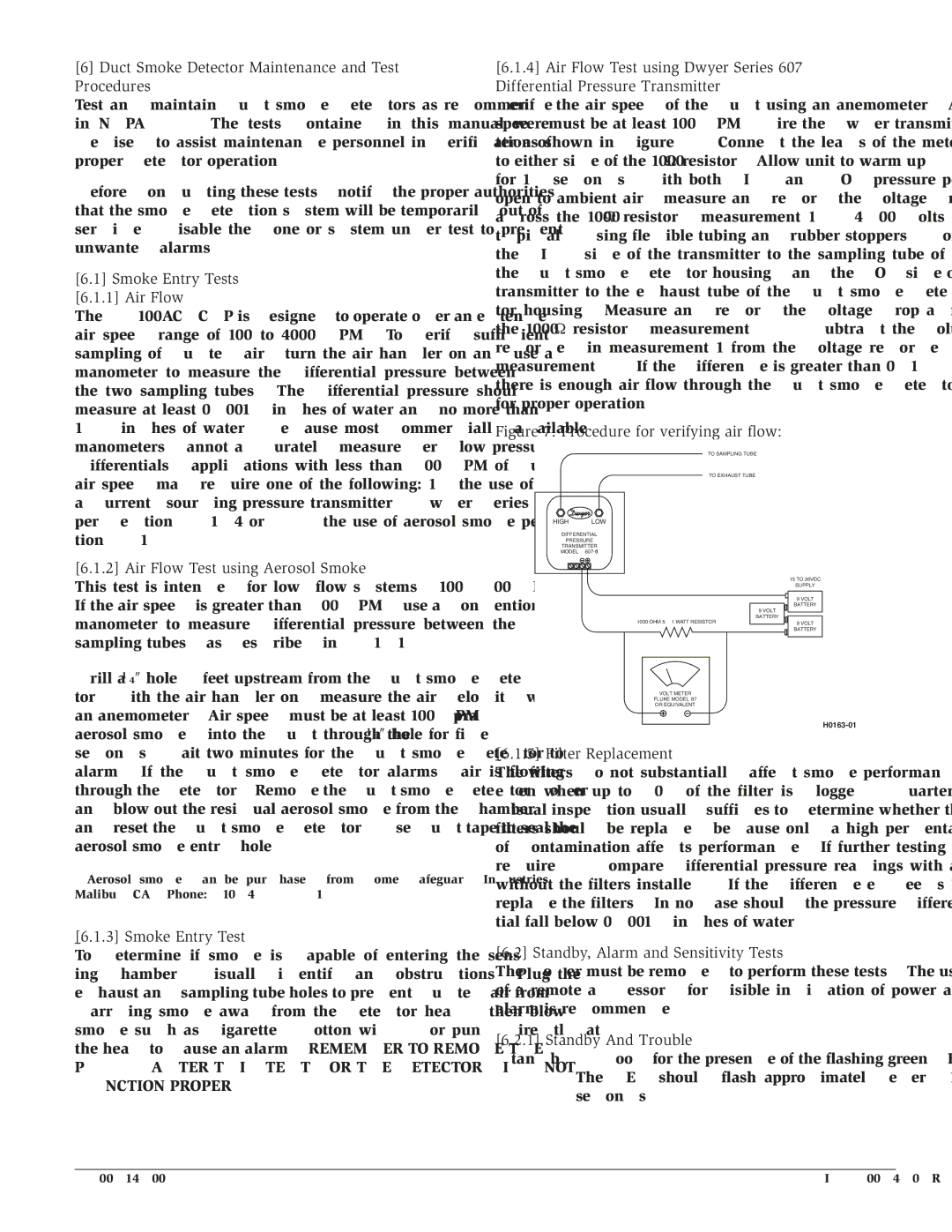
Verify the air speed of the duct using an anemometer. Air speed must be at least 100 FPM. Wire the Dwyer transmit- ter as shown in Figure 7. Connect the leads of the meter to either side of the 1000Ω resistor. Allow unit to warm up for 15 seconds. With both HIGH and LOW pressure ports open to ambient air, measure and record the voltage drop across the 1000Ω resistor (measurement 1), 4.00 volts is typical. Using flexible tubing and rubber stoppers, connect the HIGH side of the transmitter to the sampling tube of the duct smoke detector housing, and the LOW side of the transmitter to the exhaust tube of the duct smoke detec- tor housing. Measure and record the voltage drop across the 1000Ω resistor (measurement 2). Subtract the voltage recorded in measurement 1 from the voltage recorded in measurement 2. If the difference is greater than 0.15 volts, there is enough air flow through the duct smoke detector for proper operation.

Figure 7. Procedure for verifying air flow:

TO SAMPLING TUBE

TO EXHAUST TUBE

HIGH LOW

DIFFERENTIAL

PRESSURE

TRANSMITTER

MODEL #607-01

15 TO 36VDC

SUPPLY

9 VOLT

BATTERY

9 VOLT

BATTERY

1000 OHM 5% 1 WATT RESISTOR

9 VOLT


BATTERY

VOLT METER

FLUKE MODEL 87

OR EQUIVALENT

H0163-01

[6.1.5] Filter Replacement

The filters do not substantially affect smoke performance even when up to 90% of the filter is clogged. Quarterly visual inspection usually suffices to determine whether the filters should be replaced because only a high percentage of contamination affects performance. If further testing is required, compare differential pressure readings with and without the filters installed. If the difference exceeds 10% replace the filters. In no case should the pressure differen- tial fall below 0.0015 inches of water.

[6.2] Standby, Alarm and Sensitivity Tests

The cover must be removed to perform these tests. The use of a remote accessory for visible indication of power and alarm is recommended.

[6.2.1] Standby And Trouble

Standby — Look for the presence of the flashing green LED. The LED should flash approximately every 10 seconds.

D200-14-00

5

I56-0084-08R

Page 5
Image 5
System Sensor DH100ACDCLP specifications Duct Smoke Detector Maintenance and Test Procedures, Smoke Entry Tests Air Flow

DH100ACDCLP specifications

The System Sensor DH100ACDCLP is a cutting-edge addressable heat detector renowned for its advanced features and reliability in fire safety systems. Designed to meet various application requirements, this device excels in environments prone to false alarms while ensuring efficient fire detection.

One of the DH100ACDCLP’s main features is its advanced thermal sensing technology. This device utilizes a combination of fixed temperature and rate-of-rise sensing methods, allowing it to accurately detect abnormal heat levels in its surroundings. The fixed temperature feature triggers an alarm when the ambient temperature exceeds a predetermined threshold. Meanwhile, the rate-of-rise detection monitors rapid temperature increases, making it ideal for applications like kitchens, attics, and mechanical rooms where combustibles may not be immediately visible.

The DH100ACDCLP also incorporates an innovative addressable technology. This allows the device to communicate directly with the fire alarm control panel, providing precise location information and reducing response times during emergencies. By having each detector uniquely identified, facility managers can easily pinpoint which unit has triggered an alarm, streamlining response and ensuring the right areas are addressed swiftly.

Another notable characteristic of the DH100ACDCLP is its robust design, capable of operating in a variety of challenging environments. The unit is built to withstand temperatures ranging from -40°F to 150°F (-40°C to 66°C), making it suitable for both indoor and outdoor installations. Its resilient construction ensures longevity and durability, which is crucial for maintaining reliable fire safety measures over time.

Moreover, the DH100ACDCLP is compliant with various safety and performance standards. It obtained listings from UL and other recognized certification bodies, ensuring it meets strict criteria for fire detection capabilities. This compliance reinforces its credibility and effectiveness in safeguarding lives and property.

In addition to its technical features, the DH100ACDCLP is designed for straightforward installation and maintenance. Its user-friendly interface allows both installers and end-users to navigate settings and conduct routine checks with ease, ensuring that the system remains functional and reliable.

In summary, the System Sensor DH100ACDCLP stands out as a sophisticated heat detector, combining innovative thermal sensing technologies with an addressable communication system. This ensures precise detection, rapid response, and adaptability to various environments, all while maintaining compliance with safety standards. It is an indispensable component of modern fire detection systems, providing peace of mind to property owners and facility managers alike.