DH400ACDCP specifications
The System Sensor DH400ACDCP is a cutting-edge addressable smoke and heat detector specifically designed for commercial and industrial applications. Its advanced detection capabilities ensure a high level of safety in various environments, making it an essential component of modern fire alarm systems.One of the standout features of the DH400ACDCP is its dual-sensing technology. This device combines both smoke and heat detection in a single unit, allowing for a more comprehensive approach to fire safety. The smoke detection is performed using a photoelectric sensor, which effectively identifies smoldering fires that produce a large amount of smoke, while the heat detector is designed to respond to rapid temperature increases and fixed temperature thresholds. This dual functionality ensures early notification in the event of a fire, enabling timely response.
The DH400ACDCP also incorporates System Sensor’s innovative analytics technology. This feature utilizes advanced algorithms to minimize false alarms while maintaining sensitivity to actual fire threats. By analyzing environmental conditions and historical data, the detector can distinguish between normal activities and potential fire indicators, thus reducing unnecessary interruptions.
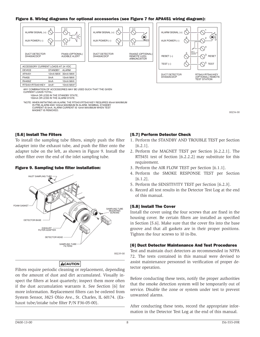
In terms of installation and maintenance, the DH400ACDCP is designed for ease of use. It features a robust addressable communication system, which allows for straightforward integration into existing fire alarm panels. The unit can be easily configured through the panel, providing flexibility in customizing notifications and response protocols. Its durable construction ensures reliability, while routine diagnostics capabilities help monitor device health and facilitate maintenance efforts.
Another significant characteristic of the DH400ACDCP is its compatibility with system monitoring and control platforms. The detector can report its status and any potential issues directly to centralized monitoring stations, enabling rapid response to emergencies or maintenance needs. By integrating with modern building management systems, the DH400ACDCP contributes to an overall intelligent safety infrastructure.
Overall, the System Sensor DH400ACDCP offers a cutting-edge solution for fire safety in various environments, combining advanced detection technology, ease of integration, and robust performance. With its focus on minimizing false alarms while ensuring reliable detection, the DH400ACDCP stands as a critical asset for maintaining safety in commercial and industrial spaces.

