I9 specifications
The Tannoy I9 is a powerful and versatile loudspeaker designed for both professional studio applications and high-end home audio systems. Renowned for its exceptional sound quality and build, the I9 is a testament to Tannoy’s long-standing reputation in the audio industry, delivering a listening experience that is both dynamic and immersive.One of the standout features of the Tannoy I9 is its dual-concentric driver technology. This patented design places the high-frequency driver at the center of the low-frequency driver, allowing for phase coherence and a more accurate reproduction of sound. As a result, the I9 produces a wide soundstage and exceptional imaging, making it an ideal choice for critical listening environments.
The I9’s construction is robust, featuring a high-quality MDF cabinet that minimizes resonance and enhances acoustic performance. The cabinet design includes internal bracing which further reduces vibration and distortion, ensuring clarity in both vocals and instruments. The speaker is available in various finishes, allowing it to seamlessly blend into any environment, whether it be a modern studio or a classic home setting.
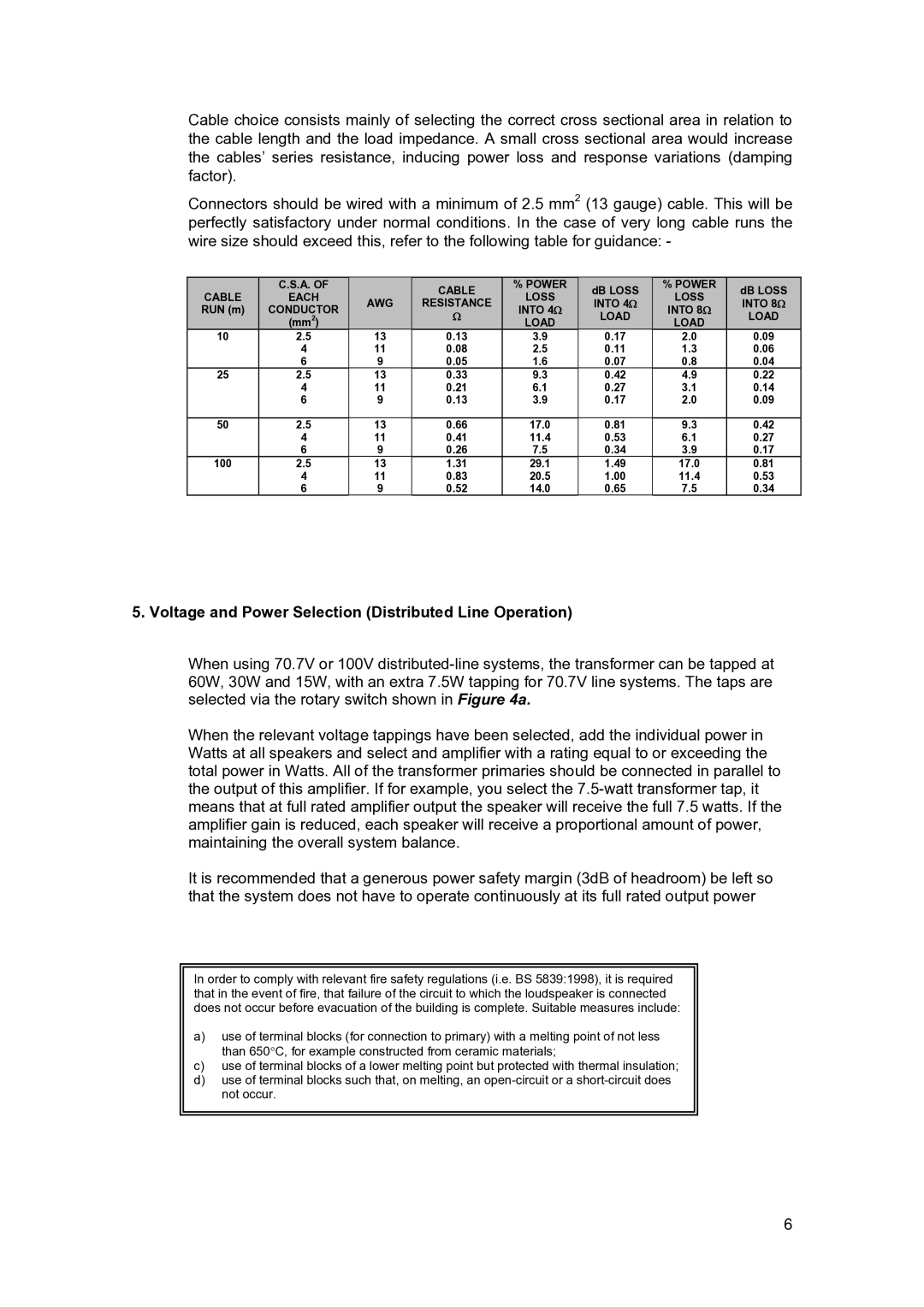
In terms of connectivity, the Tannoy I9 is equipped with professional-grade inputs, including XLR and TRS connections, making it suitable for a wide range of audio setups. The built-in amplification is carefully matched to the drivers, providing optimal performance while maintaining efficiency. The amplifier features adjustable controls for level, EQ, and crossover settings, allowing users to tailor the sound to their specific preferences and room acoustics.
Another notable characteristic of the I9 is its attention to detail in frequency response. The speaker is capable of delivering a wide frequency range, from deep bass notes to crystal-clear highs, making it suitable for various genres of music and audio content. This full-range capability ensures that listeners experience every nuance of a recording, from the thump of a bass guitar to the delicacy of a violin.
For those seeking a complete audio solution, the Tannoy I9 can be easily integrated with other components, such as subwoofers, allowing for greater depth and richness in sound. This flexibility makes the I9 an appealing choice for both casual listeners and seasoned audiophiles alike.
Overall, the Tannoy I9 stands out for its exceptional engineering, sophisticated design, and remarkable sound quality, making it a worthy investment for anyone serious about enjoying high-fidelity audio reproduction. Whether for professional applications or personal enjoyment, the Tannoy I9 promises to deliver a captivating listening experience that is hard to match.

