US-224 specifications
The Tascam US-224 is a compact and versatile audio interface designed to meet the needs of musicians, podcasters, and home recording enthusiasts. Launched as part of Tascam's innovative range of products, the US-224 is recognized for its ease of use, portability, and impressive sound quality, making it an ideal choice for those looking to record in various environments.One of the standout features of the US-224 is its capability to connect directly to a computer via USB, allowing users to harness the power of digital audio workstations (DAWs). This seamless connectivity ensures low-latency performance, enabling users to record and monitor audio in real-time without distracting delays. The interface is compatible with both Mac and Windows operating systems, which broadens its appeal to a wide user base.
The US-224 is equipped with two high-quality microphone preamps, providing sufficient headroom for capturing a wide range of audio sources. These preamps are known for their clear, detailed sound reproduction, making them suitable for various applications, from vocal recordings to instrument captures. Additionally, the interface features phantom power for condenser microphones, ensuring flexibility in microphone choice.
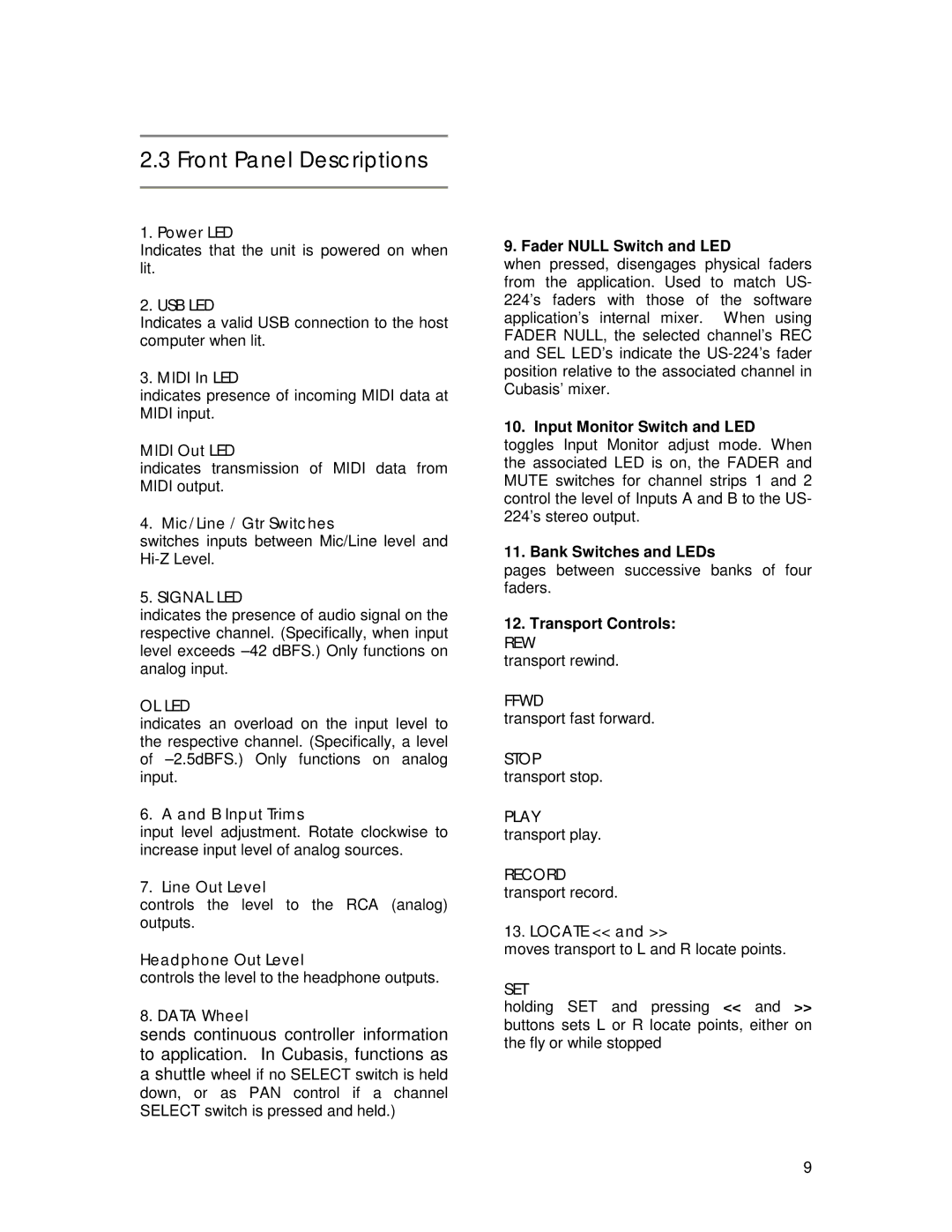
Users will appreciate the integrated mixer on the US-224, which allows for easy control of audio levels and monitoring. The interface includes insert points and line inputs, offering further options for routing signals, whether for instruments or external processing equipment. The built-in MIDI input and output ports also enhance the interface’s versatility, allowing users to connect MIDI controllers and other devices for comprehensive music production.
The compact design of the US-224 makes it highly portable, a significant advantage for mobile recording setups. This lightweight interface can easily fit into a laptop bag, enabling users to capture high-quality audio anywhere. Furthermore, the durable construction of the unit ensures it can withstand the rigors of travel.
In summary, the Tascam US-224 stands out as a reliable audio interface packed with essential features for recording enthusiasts. Its excellent sound quality, robust connectivity options, and user-friendly interface make it a valuable tool for anyone looking to create professional-level recordings effortlessly. Whether in a studio or on the go, the Tascam US-224 provides an unyielding performance that meets the demands of modern audio production.
