Connecting Accessory Devices to Your TV
CONNECTING A VCR AND CABLE BOX
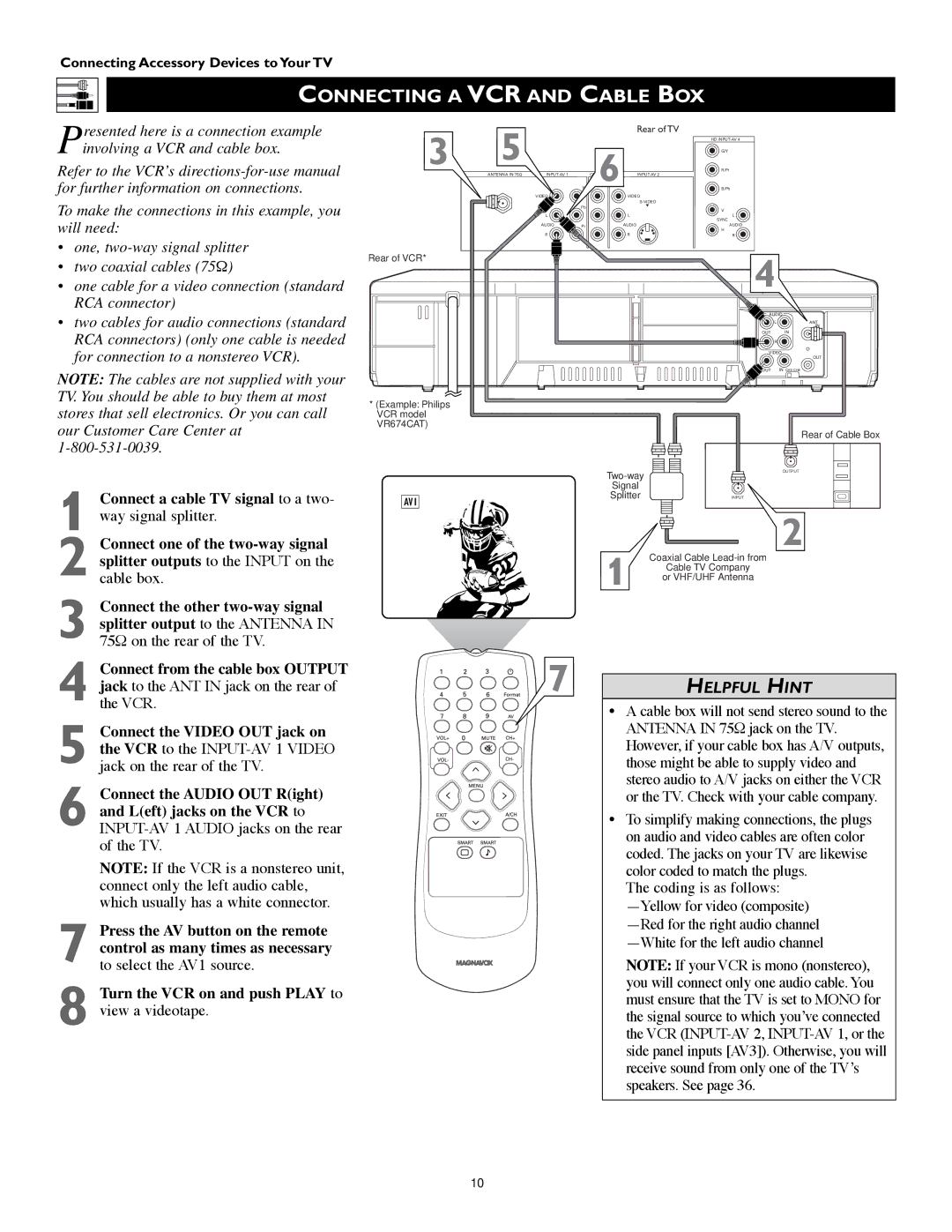
Presented here is a connection example involving a VCR and cable box.
Refer to the VCR’s
To make the connections in this example, you will need:
•one,
•two coaxial cables (75Ω)
•one cable for a video connection (standard RCA connector)
•two cables for audio connections (standard RCA connectors) (only one cable is needed for connection to a nonstereo VCR).
NOTE: The cables are not supplied with your TV. You should be able to buy them at most stores that sell electronics. Or you can call our Customer Care Center at
1 Connect a cable TV signal to a two- way signal splitter.
2 Connect one of the
3 Connect the other
3 | 5 |
|
| Rear of TV |
|
|
|
|
| R/Pr |
| ||
|
|
|
|
| HD |
|
|
|
|
| 6 | G/Y |
|
| ANTENNA IN 75Ω | Y | B/Pb |
| ||
|
| VIDEO |
| VIDEO |
|
|
|
|
|
|
|
| |
|
|
| Pb | L |
|
|
|
|
|
| V |
| |
|
|
|
|
|
| |
|
| L |
| L | L |
|
|
|
|
|
| SYNC |
|
|
| AUDIO | Pr | AUDIO | AUDIO |
|
|
|
|
|
| H |
|
|
| R |
| R | R |
|
Rear of VCR* |
|
|
|
| 4 |
|
|
|
|
|
|
| |
|
|
|
|
| AUDIO | |
|
|
|
|
| L | ANT |
|
|
|
|
|
| IN |
|
|
|
|
| OUT | IN |
|
|
|
|
| R |
|
|
|
|
|
| VIDEO | |
|
|
|
|
|
| OUT |
|
|
|
|
| OUT | IN CH3 CH4 |
*(Example: Philips VCR model VR674CAT)
Rear of Cable Box
OUTPUT | |
| |
Signal |
|
AV1 | Splitter | INPUT |
|
|
2
Coaxial Cable
or VHF/UHF Antenna
Connect from the cable box OUTPUT | 7 |
jack to the ANT IN jack on the rear of | |
4 the VCR. |
|
5 Connect the VIDEO OUT jack on the VCR to the
6 Connect the AUDIO OUT R(ight) and L(eft) jacks on the VCR to
NOTE: If the VCR is a nonstereo unit, connect only the left audio cable, which usually has a white connector.
7 Press the AV button on the remote control as many times as necessary to select the AV1 source.
8 Turn the VCR on and push PLAY to view a videotape.
HELPFUL HINT
•A cable box will not send stereo sound to the ANTENNA IN 75Ω jack on the TV. However, if your cable box has A/V outputs, those might be able to supply video and stereo audio to A/V jacks on either the VCR or the TV. Check with your cable company.
•To simplify making connections, the plugs on audio and video cables are often color coded. The jacks on your TV are likewise color coded to match the plugs.
The coding is as follows:
NOTE: If your VCR is mono (nonstereo), you will connect only one audio cable. You must ensure that the TV is set to MONO for the signal source to which you’ve connected the VCR
10