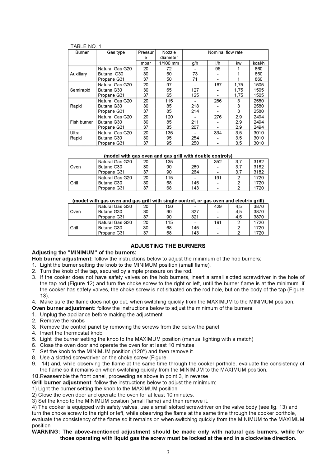
TABLE NO. 1
Burner | Gas type | Pressur | Nozzle |
| Nominal flow rate |
| |
|
| e | diameter |
|
|
|
|
|
| mbar | 1/100 mm | g/h | l/h | kw | kcal/h |
| Natural Gas G20 | 20 | 72 | - | 95 | 1 | 860 |
Auxiliary | Butane G30 | 30 | 50 | 73 | - | 1 | 860 |
| Propane G31 | 37 | 50 | 71 | - | 1 | 860 |
| Natural Gas G20 | 20 | 97 | - | 167 | 1,75 | 1505 |
Semirapid | Butane G30 | 30 | 65 | 127 | - | 1,75 | 1505 |
| Propane G31 | 37 | 65 | 125 | - | 1,75 | 1505 |
| Natural Gas G20 | 20 | 115 | - | 286 | 3 | 2580 |
Rapid | Butane G30 | 30 | 85 | 218 | - | 3 | 2580 |
| Propane G31 | 37 | 85 | 214 | - | 3 | 2580 |
| Natural Gas G20 | 20 | 120 | - | 276 | 2,9 | 2494 |
Fish burner | Butane G30 | 30 | 85 | 211 | - | 2,9 | 2494 |
| Propane G31 | 37 | 85 | 207 | - | 2,9 | 2494 |
Ultra | Natural Gas G20 | 20 | 135 | - | 334 | 3,5 | 3010 |
Rapid | Butane G30 | 30 | 95 | 254 | - | 3,5 | 3010 |
| Propane G31 | 37 | 95 | 250 | - | 3,5 | 3010 |
(model with gas oven and gas grill with double controls)
| Natural Gas G20 | 20 | 135 | - | 352 | 3,7 | 3182 |
Oven | Butane G30 | 30 | 90 | 269 | - | 3,7 | 3182 |
| Propane G31 | 37 | 90 | 264 | - | 3,7 | 3182 |
| Natural Gas G20 | 20 | 115 | - | 191 | 2 | 1720 |
Grill | Butane G30 | 30 | 68 | 145 | - | 2 | 1720 |
| Propane G31 | 37 | 68 | 143 | - | 2 | 1720 |
(model with gas oven and gas grill with single control, or gas oven and electric grill)
| Natural Gas G20 | 20 | 150 | - | 429 | 4,5 | 3870 |
Oven | Butane G30 | 30 | 90 | 327 | - | 4,5 | 3870 |
| Propane G31 | 37 | 90 | 321 | - | 4,5 | 3870 |
| Natural Gas G20 | 20 | 115 | - | 191 | 2 | 1720 |
Grill | Butane G30 | 30 | 68 | 145 | - | 2 | 1720 |
| Propane G31 | 37 | 68 | 143 | - | 2 | 1720 |
ADJUSTING THE BURNERS
Adjusting the ”MINIMUM” of the burners:
Hob burner adjustment: follow the instructions below to adjust the minimum of the hob burners:
1.Light the burner setting the knob to the MINIMUM position (small flame).
2.Turn the knob of the tap, secured by simple pressure on the rod.
3.If the cooker does not have safety valves on the hob burners, insert a small slotted screwdriver in the hole of the tap rod (Figure 12) and turn the choke screw to the right or left, until the burner flame is at the minimum; if the cooker has safety valves, the choke screw is not situated on the rod hole, but on the body of the tap (Figure 13).
4.Make sure the flame does not go out, when switching quickly from the MAXIMUM to the MINIMUM position. Oven burner adjustment: follow the instructions below to adjust the minimum of the burners:
1.Unplug the appliance before making the adjustment
2.Remove the knobs
3.Remove the control panel by removing the screws from the below the panel
4.Insert the thermostat knob
5.Light the burner setting the knob to the MAXIMUM position (manual lighting with a match)
6.Close the oven door and operate the oven for at least 10 minutes.
7.Set the knob to the MINIMUM position (120°) and then remove it.
8.Use a slotted screwdriver on the choke screw (Figure
9.14) and, while observing the flame at the same time through the cooker porthole, evaluate the consistency of the flame so it remains on when switching quickly from the MINIMUM to the MAXIMUM position.
10.Reassemble the front panel, proceeding as above in point 3, in reverse Grill burner adjustment: follow the instructions below to adjust the minimum:
1)Light the burner setting the knob to the MAXIMUM position.
2)Close the oven door and operate the oven for at least 10 minutes.
3)Set the knob to the MINIMUM position (small flame) and then remove it.
4)The cooker is equipped with safety valves, use a small slotted screwdriver on the valve body (see fig. 13) and turn the choke screw to the right or left, while observing the flame at the same time through the cooker porthole, evaluate the consistency of the flame so it remains on when switching quickly from the MINIMUM to the MAXIMUM position.
WARNING: The
3