REPLACING COMPONENTS
Before carrying out any maintenance, unplug the appliance from the gas and electricity mains.
To replace components such as knobs and burner heads, simply remove from their housing without disassembling any part of the cooker.
To replace components such as burner holders, taps and electrical components, proceed as described in the section on adjusting burners. If replacing the gas tap or thermostat, the two rear ramp brackets need to be disassembled by removing the 4 screws (2 screws per bracket), which secure it to the rest of the cooker; remove the 2 screws securing the bracket of the taps to the control panel support, after removing the knobs. If the gas or electric thermostat is to be replaced, the rear cooker protection also needs to be removed. Remove the screws, to take out and put back the thermostat bulb.
To replace the oven light, unscrew the light cover inside the oven (Figure 16).
NOTE: Before replacing the light, unplug the appliance from the mains.
NOTE: If replacing the power supply lead, the installer should keep the earthing wire longer than the live wires and follow instructions for electrical connections.
USE AND MAINTENANCE MANUAL
DESCRIPTION OF HOB PARTS
Warning:
Oven and grill burners shall not be used simultaneously.
Size of gas burners Table 3
BURNER | SIZE (mm) | |
1 | Auxiliary | ∅ 50 |
2 | Semirapid | ∅ 70 |
3 | Rapid | −{}−∅ 95 |
4 | Triple ring | ∅ 130 |
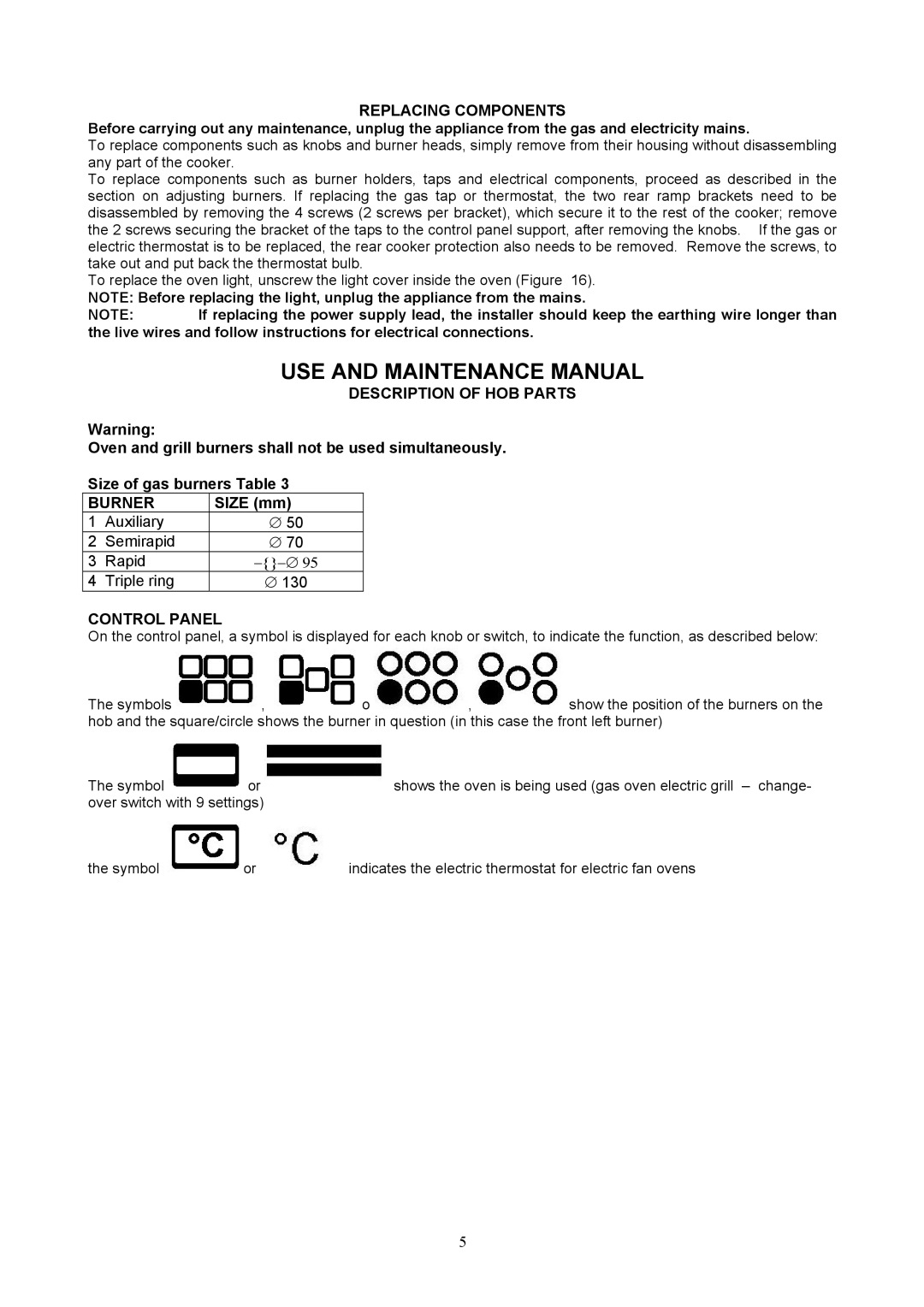
CONTROL PANEL
On the control panel, a symbol is displayed for each knob or switch, to indicate the function, as described below:
The symbols  ,
,  o
o ,
, show the position of the burners on the hob and the square/circle shows the burner in question (in this case the front left burner)
The symbol ![]() or
or shows the oven is being used (gas oven electric grill – change- over switch with 9 settings)
the symbol ![]() or
or![]() indicates the electric thermostat for electric fan ovens
indicates the electric thermostat for electric fan ovens
5
