GB Installation
Important
INSTALLATION AND SETUP SHOULD BE CARRIED OUT BY AN AUTHORISED
TECHNICIAN ACCORDING TO CURRENT INSTALLATION STANDARDS.
Positioning the hobs
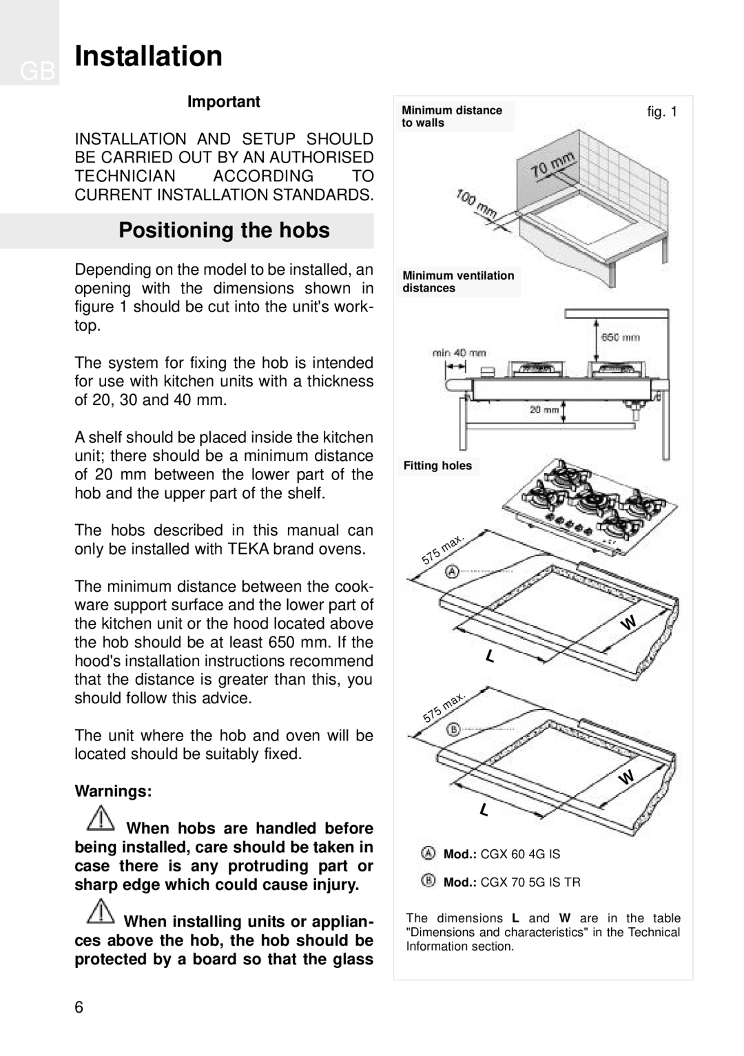
Depending on the model to be installed, an opening with the dimensions shown in figure 1 should be cut into the unit's work- top.
The system for fixing the hob is intended for use with kitchen units with a thickness of 20, 30 and 40 mm.
A shelf should be placed inside the kitchen unit; there should be a minimum distance of 20 mm between the lower part of the hob and the upper part of the shelf.
The hobs described in this manual can only be installed with TEKA brand ovens.
The minimum distance between the cook- ware support surface and the lower part of the kitchen unit or the hood located above the hob should be at least 650 mm. If the hood's installation instructions recommend that the distance is greater than this, you should follow this advice.
The unit where the hob and oven will be located should be suitably fixed.
Warnings:
![]() When hobs are handled before being installed, care should be taken in case there is any protruding part or sharp edge which could cause injury.
When hobs are handled before being installed, care should be taken in case there is any protruding part or sharp edge which could cause injury.
![]() When installing units or applian- ces above the hob, the hob should be protected by a board so that the glass
When installing units or applian- ces above the hob, the hob should be protected by a board so that the glass
Minimum distance | fig. 1 |
to walls |
|
Minimum ventilation distances
Fitting holes
| . |
| x |
| a |
| m |
| 5 |
7 | |
5 |
|
W
L
. x a m 5 7 5
W
L
Mod.: CGX 60 4G IS
Mod.: CGX 70 5G IS TR
The dimensions L and W are in the table "Dimensions and characteristics" in the Technical Information section.
6