2. Installation
This section contains the necessary instructions to assist in placing the
2.1. Receiving Inspection
Carefully unpack the Hastings product(s). Inspect for any obvious signs of damage to the shipment. Immediately advise the carrier who delivered the shipment if any damage is suspected. Check each component shipped with the packing list. Insure that all parts listed are present. Other equipment or accessories will be listed separately.
2.2. Piezo Transducer (760s) Installation
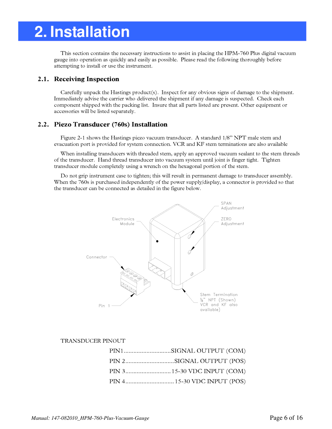
Figure 2-1 shows the Hastings piezo vacuum transducer. A standard 1/8” NPT male stem and
evacuation port is provided for system connection. VCR and KF stem terminations are also available
When installing transducers with threaded stem, apply an approved vacuum sealant to the stem threads of the transducer. Hand thread transducer into vacuum system until joint is finger tight. Tighten transducer module completely using a wrench on the hexagonal portion of the stem.
Do not grip instrument case to tighten; this will result in permanent damage to transducer assembly. When the 760s is purchased independently of the power supply/display, a connector is provided so that the transducer can be connected as detailed in the figure below.
TRANSDUCER PINOUT |
|
PIN1 | SIGNAL OUTPUT (COM) |
PIN 2 | SIGNAL OUTPUT (POS) |
PIN 3 | |
PIN 4 |
Manual: | Page 6 of 16 |
