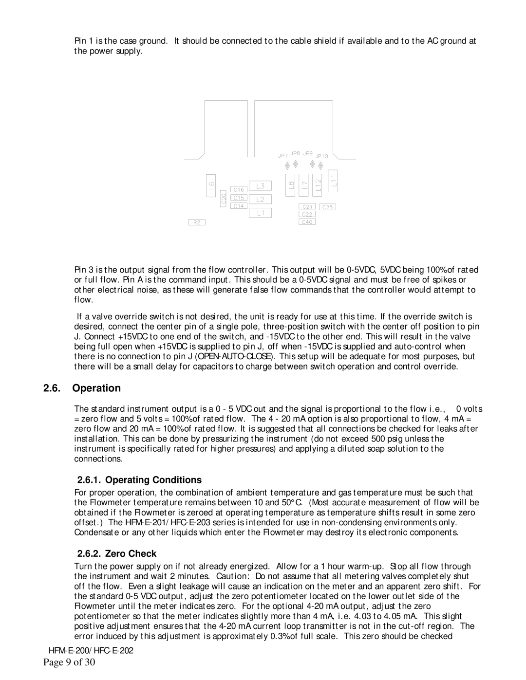
Pin 1 is the case ground. It should be connected to the cable shield if available and to the AC ground at the power supply.

Pin 3 is the output signal from the flow controller. This output will be 0-5VDC, 5VDC being 100% of rated or full flow. Pin A is the command input. This should be a 0-5VDC signal and must be free of spikes or other electrical noise, as these will generate false flow commands that the controller would attempt to flow.

If a valve override switch is not desired, the unit is ready for use at this time. If the override switch is desired, connect the center pin of a single pole, three-position switch with the center off position to pin J. Connect +15VDC to one end of the switch, and -15VDC to the other end. This will result in the valve being full open when +15VDC is supplied to pin J, off when -15VDC is supplied and auto-control when there is no connection to pin J (OPEN-AUTO-CLOSE). This setup will be adequate for most purposes, but there will be a small delay for capacitors to charge between switch operation and control override.

2.6.Operation

The standard instrument output is a 0 - 5 VDC out and the signal is proportional to the flow i.e., 0 volts = zero flow and 5 volts = 100% of rated flow. The 4 - 20 mA option is also proportional to flow, 4 mA = zero flow and 20 mA = 100% of rated flow. It is suggested that all connections be checked for leaks after installation. This can be done by pressurizing the instrument (do not exceed 500 psig unless the instrument is specifically rated for higher pressures) and applying a diluted soap solution to the connections.

2.6.1. Operating Conditions

For proper operation, the combination of ambient temperature and gas temperature must be such that the Flowmeter temperature remains between 10 and 50°C. (Most accurate measurement of flow will be obtained if the Flowmeter is zeroed at operating temperature as temperature shifts result in some zero offset.) The HFM-E-201/HFC-E-203 series is intended for use in non-condensing environments only. Condensate or any other liquids which enter the Flowmeter may destroy its electronic components.

2.6.2. Zero Check

Turn the power supply on if not already energized. Allow for a 1 hour warm-up. Stop all flow through the instrument and wait 2 minutes. Caution: Do not assume that all metering valves completely shut off the flow. Even a slight leakage will cause an indication on the meter and an apparent zero shift. For the standard 0-5 VDC output, adjust the zero potentiometer located on the lower outlet side of the Flowmeter until the meter indicates zero. For the optional 4-20 mA output, adjust the zero potentiometer so that the meter indicates slightly more than 4 mA, i.e. 4.03 to 4.05 mA. This slight positive adjustment ensures that the 4-20 mA current loop transmitter is not in the cut-off region. The error induced by this adjustment is approximately 0.3% of full scale. This zero should be checked

HFM-E-200/HFC-E-202

Page 9 of 30

Page 9
Image 9
Teledyne HFM-E-200, HFC-E-202 instruction manual Operation, Operating Conditions, Zero Check

HFC-E-202, HFM-E-200 specifications

Teledyne HFC-E-202 and HFM-E-200 are advanced flow meters designed to provide precise measurement and monitoring of gas and liquid flows in various industrial applications. Both devices are engineered to meet the demands of sectors such as petrochemicals, pharmaceuticals, and food and beverage, where accuracy and reliability are paramount.

The Teledyne HFC-E-202 is a highly sensitive flow meter that utilizes a thermal mass flow measurement technology. This technology enables the HFC-E-202 to accurately measure the mass flow rate of gases regardless of temperature and pressure conditions. One of its key features is its ability to provide high precision and fast response times, making it suitable for applications that require immediate data feedback. The device is also equipped with advanced diagnostics that allow users to monitor the health of the system and identify potential issues before they escalate.

On the other hand, the HFM-E-200 is particularly renowned for its versatility in measuring both gas and liquid flows. It employs differential pressure technology, which is highly effective in a wide range of operating conditions. The HFM-E-200 incorporates a robust design that can withstand harsh environments, ensuring longevity and reliability. Its user-friendly interface allows for easy configuration and monitoring, catering to both novice and experienced technicians.

Both flow meters feature digital output options, facilitating seamless integration with existing control systems. This enables real-time data acquisition and monitoring, enhancing process control and efficiency. Furthermore, their compact design minimizes installation space, allowing for easy placement in tight operational areas.

In terms of safety and compliance, both the HFC-E-202 and HFM-E-200 are designed to meet strict industry standards, ensuring they can be deployed in critical applications without compromising safety.

In conclusion, Teledyne HFC-E-202 and HFM-E-200 flow meters stand out due to their innovative technologies, accuracy, and durability. Their unique features position them as essential tools for a variety of industrial sectors, enhancing operational efficiency and ensuring reliable fluid flow measurement. With Teledyne’s commitment to quality and innovation, users can trust that these devices will meet their demands both now and in the future.