SYMPTOM: Flow controller oscillates.

CAUSE: Flow controller not adjusted for the dynamics of the flow system.

ACTION: Check upstream and downstream pressures. The gas supply regulator should not have excessive lockup when flow shuts off. Also ensure that there is not a large drop in pressure between the regulator and the instrument due to line resistance. Oscillations can also be caused if a large flow restriction is pneumatically close to the downstream end of the flow controller. The differential pressure across the unit must be between the values specifications on the original order.

SYMPTOM: Little or no flow, even with a maximum SetPoint value.

CAUSE: Plugged orifice.

ACTION: Verify the presence of a pressure across the instrument. If present, shut off gas supply and power supply. Remove orifice per Section 4.9. Examine orifice. If plugged, clean or replace as applicable. Reassemble valve.

SYMPTOM: Flowmeter reads other than 0.00 VDC with no flow, or there is a small flow when Flowmeter reads 0.00 VDC.

CAUSE: ZERO potentiometer is out of adjustment.

ACTION: Shut off all flow. Adjust ZERO potentiometer until output reads 0.00 VDC.

SYMPTOM: Flowmeter out of calibration and nonlinear.

CAUSE: Leaks in gas inlet or outlet fittings.

ACTION: Check all fittings for leaks by placing soap solution on all fittings between gas supply and final destination of gas. Check Flowmeter for leaks. Replace “O” rings if required or recalibrate as necessary.

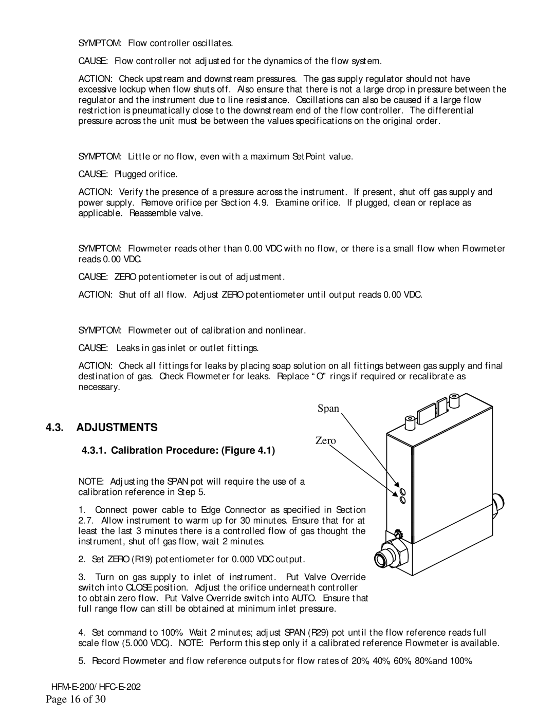
Span

4.3. ADJUSTMENTS

Zero

4.3.1. Calibration Procedure: (Figure 4.1)

NOTE: Adjusting the SPAN pot will require the use of a calibration reference in Step 5.

1. Connect power cable to Edge Connector as specified in Section 2.7. Allow instrument to warm up for 30 minutes. Ensure that for at least the last 3 minutes there is a controlled flow of gas thought the instrument, shut off gas flow, wait 2 minutes.

2. Set ZERO (R19) potentiometer for 0.000 VDC output.

3. Turn on gas supply to inlet of instrument. Put Valve Override switch into CLOSE position. Adjust the orifice underneath controller to obtain zero flow. Put Valve Override switch into AUTO. Ensure that full range flow can still be obtained at minimum inlet pressure.

4.Set command to 100%. Wait 2 minutes; adjust SPAN (R29) pot until the flow reference reads full

scale flow (5.000 VDC). NOTE: Perform this step only if a calibrated reference Flowmeter is available.

5.Record Flowmeter and flow reference outputs for flow rates of 20%, 40%, 60%, 80% and 100%.

HFM-E-200/HFC-E-202

Page 16 of 30

Page 16
Image 16
Teledyne HFC-E-202, HFM-E-200 instruction manual Adjustments, Calibration Procedure Figure

HFC-E-202, HFM-E-200 specifications

Teledyne HFC-E-202 and HFM-E-200 are advanced flow meters designed to provide precise measurement and monitoring of gas and liquid flows in various industrial applications. Both devices are engineered to meet the demands of sectors such as petrochemicals, pharmaceuticals, and food and beverage, where accuracy and reliability are paramount.

The Teledyne HFC-E-202 is a highly sensitive flow meter that utilizes a thermal mass flow measurement technology. This technology enables the HFC-E-202 to accurately measure the mass flow rate of gases regardless of temperature and pressure conditions. One of its key features is its ability to provide high precision and fast response times, making it suitable for applications that require immediate data feedback. The device is also equipped with advanced diagnostics that allow users to monitor the health of the system and identify potential issues before they escalate.

On the other hand, the HFM-E-200 is particularly renowned for its versatility in measuring both gas and liquid flows. It employs differential pressure technology, which is highly effective in a wide range of operating conditions. The HFM-E-200 incorporates a robust design that can withstand harsh environments, ensuring longevity and reliability. Its user-friendly interface allows for easy configuration and monitoring, catering to both novice and experienced technicians.

Both flow meters feature digital output options, facilitating seamless integration with existing control systems. This enables real-time data acquisition and monitoring, enhancing process control and efficiency. Furthermore, their compact design minimizes installation space, allowing for easy placement in tight operational areas.

In terms of safety and compliance, both the HFC-E-202 and HFM-E-200 are designed to meet strict industry standards, ensuring they can be deployed in critical applications without compromising safety.

In conclusion, Teledyne HFC-E-202 and HFM-E-200 flow meters stand out due to their innovative technologies, accuracy, and durability. Their unique features position them as essential tools for a variety of industrial sectors, enhancing operational efficiency and ensuring reliable fluid flow measurement. With Teledyne’s commitment to quality and innovation, users can trust that these devices will meet their demands both now and in the future.