Balanced |
|
|
|
|
|
|
Audio | INPUT | PINS |
|
| Antenna |
|
|
| RadioComTM |
| |||
| RTS 1 | Unbalanced | ||||
| RTS 2 | Audio |
|
| AC/DC | |
| TELEX |
|
| WIRELESS IFB TRANSMITTER |
| FCC ID: B5DM524 |
| IC: |
| S.N.: XXXXXX |
Telex Communications, Inc. | Telex Communications, Inc. Made in USA |
P/N: 804182 | |
Made in U.S.A. |
|
1 | 2 | 3 | 4 |
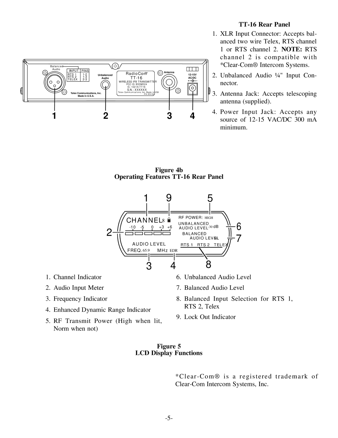
TT-16 Rear Panel
1.XLR Input Connector: Accepts bal- anced two wire Telex, RTS channel 1 or RTS channel 2. NOTE: RTS channel 2 is compatible with
2.Unbalanced Audio ¼" Input Con- nector.
![]() 3. Antenna Jack: Accepts telescoping antenna (supplied).
3. Antenna Jack: Accepts telescoping antenna (supplied).
4.Power Input Jack: Accepts any source of
Figure 4b
Operating Features TT-16 Rear Panel
1 | 9 |
| 5 |
| |
CHANNEL 8 | RF POWER: HIGH |
| |||
UNBALANCED | 6 | ||||
+3 +6 | |||||
AUDIO LEVEL | |||||
2 |
|
| |||
| BALANCED |
| 7 | ||
|
| AUDIO LEVEL | |||
|
|
| |||
AUDIO LEVEL | RTS 1 RTS 2 | TELEX |
| ||
FREQ. 65.9 | MHz EDR |
|
|
| |
3
1.Channel Indicator
2.Audio Input Meter
3.Frequency Indicator
4.Enhanced Dynamic Range Indicator
5.RF Transmit Power (High when lit, Norm when not)
48
6.Unbalanced Audio Level
7.Balanced Audio Level
8.Balanced Input Selection for RTS 1, RTS 2, Telex
9.Lock Out Indicator
Figure 5