|
|
Audio Input: Female XLR |
|
RTS 1 Selected | Line impedance 200 Ω / Level adjustable |
RTS 2 Selected | Line impedance 200 Ω / Level adjustable |
Telex Selected | Line impedance 300 Ω / Level adjustable |
Unbalanced Audio Input | 10K Ω input impedance/10 |
RF Power Switch | 50mW in “Hi”, approx. 5mW in “Low” |
AGC Range | 30 dB |
| |
Normal | 58 dB |
EDR Enabled | 77 dB |
115μS | |
Maximum Deviation | ±25 kHz |
Frequency Control Crystal | |
Available Frequencies | See Table 1, page 2 |
Max. Transmitter Output Power | 50 mW |
Power Requirements | |
Dimensions | 7 ½"W x 1 3/4"H x 6 7/8"D |
FCC ID | B5DM524 |
EQUIPMENT SET-UP AND OPERATION
TT-16 SYNTHESIZED
TRANSMITTER
UNPACKING: Unpack your Wireless IFB system. If there are any damages or shortages, refer to the "War- ranty Service Information" card.
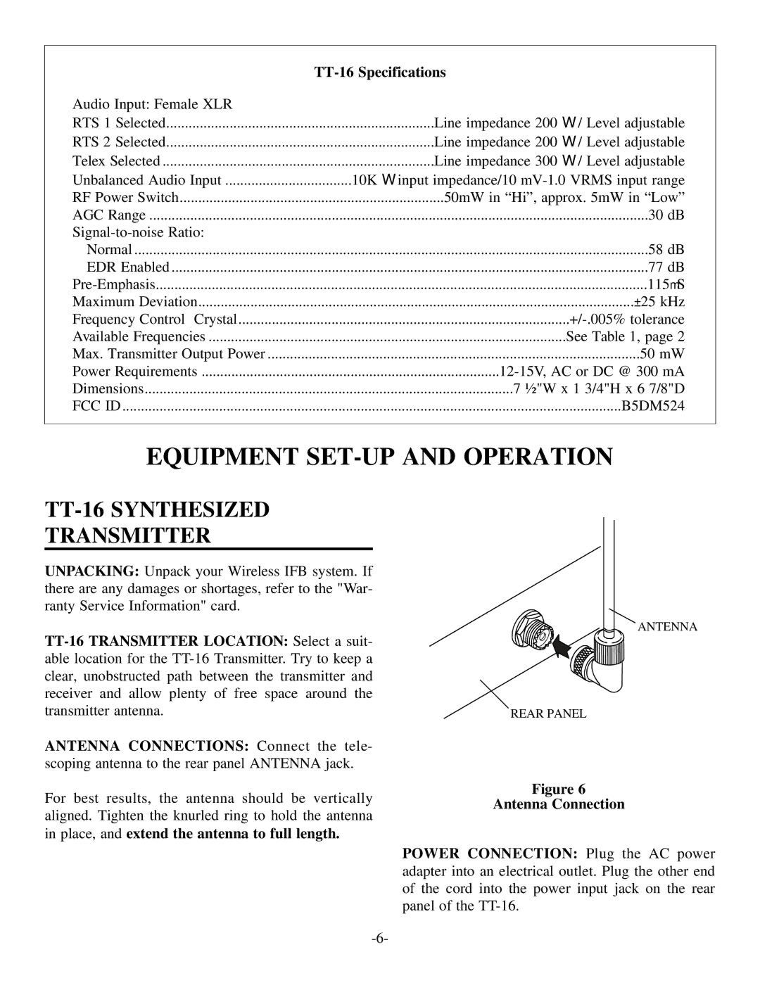
ANTENNA CONNECTIONS: Connect the tele- scoping antenna to the rear panel ANTENNA jack.
For best results, the antenna should be vertically aligned. Tighten the knurled ring to hold the antenna in place, and extend the antenna to full length.
ANTENNA
REAR PANEL
Figure 6
Antenna Connection
POWER CONNECTION: Plug the AC power adapter into an electrical outlet. Plug the other end of the cord into the power input jack on the rear panel of the