2.Install the previously removed screws. Insert an additional screw (provided in the parts pack) into the remaining holes. Tighten all screws securely.
3.Place the two assemblies
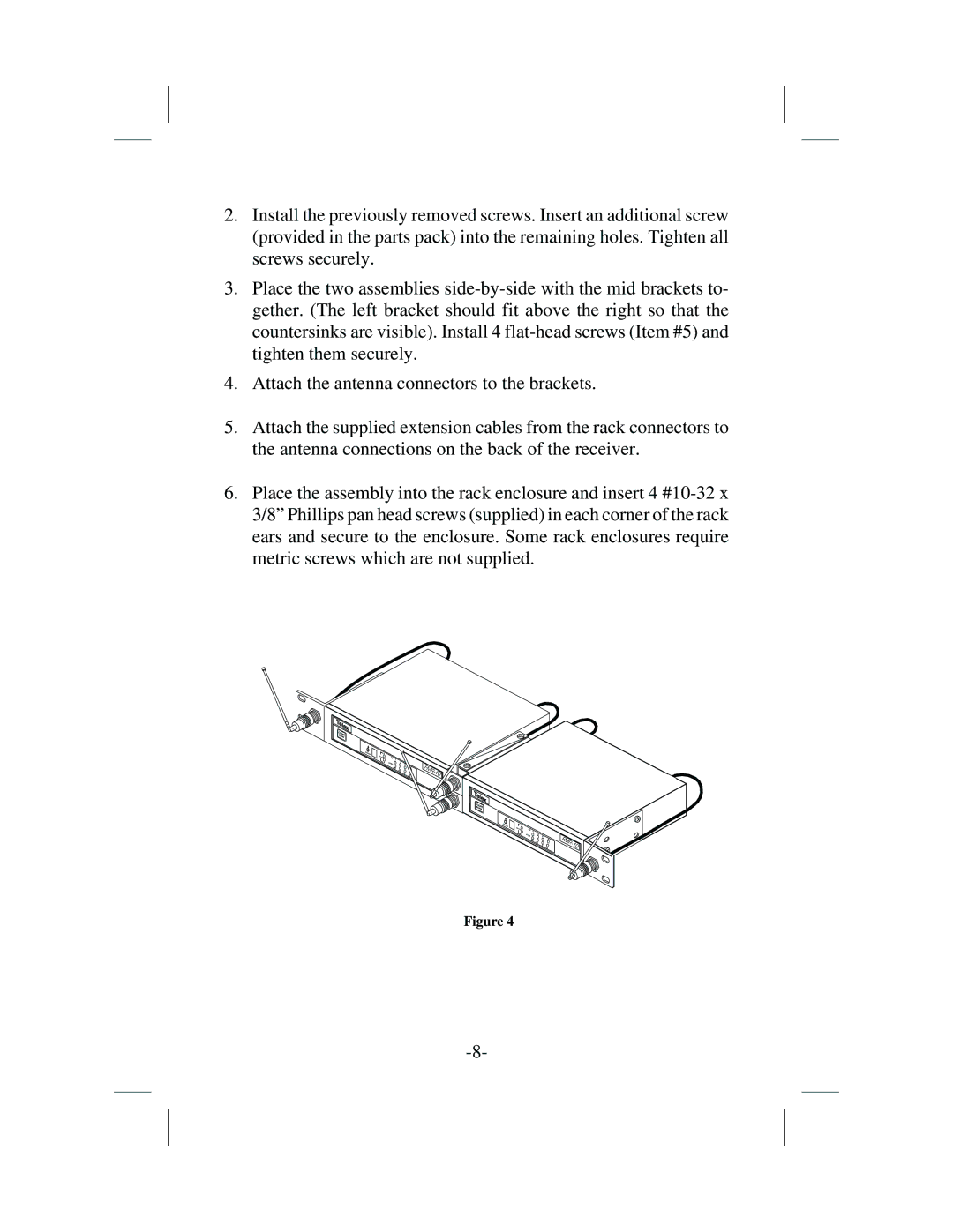
4.Attach the antenna connectors to the brackets.
5.Attach the supplied extension cables from the rack connectors to the antenna connections on the back of the receiver.
6.Place the assembly into the rack enclosure and insert 4
Channel ![]()
Diversity![]()
AUDIO
FMR-10
Channel
Diversity
Figure 4
AUDIO ![]()
![]()
![]()
![]()
![]()
![]()
![]()