3. Detailed Setup Instructions
3.1 FMR-10 Receiver Setup & Operation
1.Place the receiver where there is a clear line of sight to the area where the transmitter will be used.
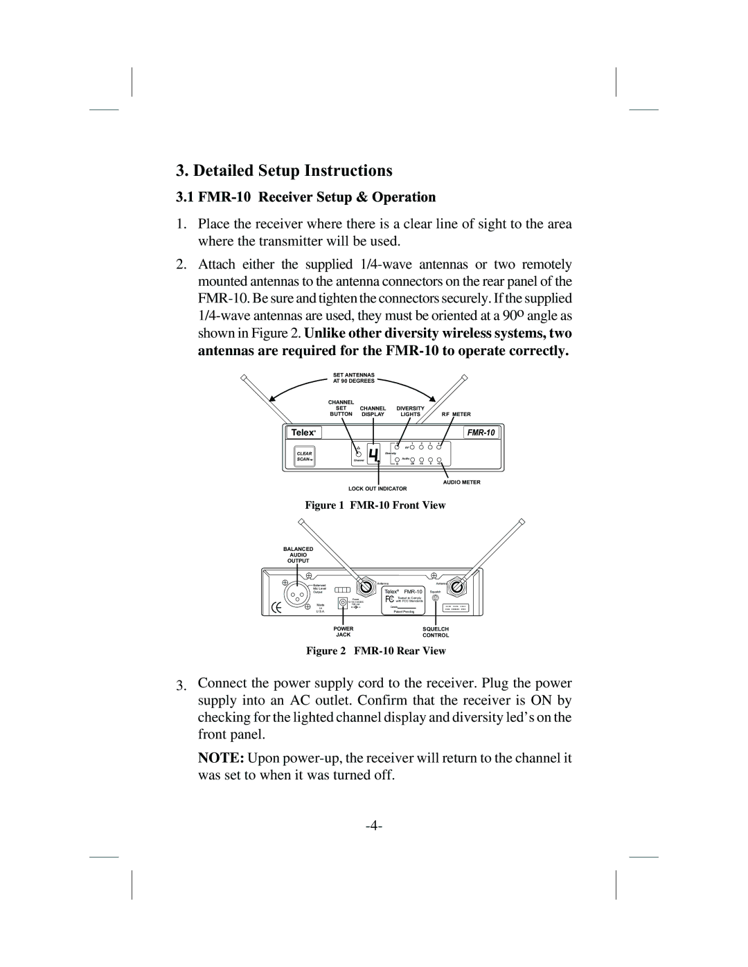
2.Attach either the supplied
SET ANTENNAS
AT 90 DEGREES
CHANNEL |
|
|
|
|
|
|
SET | CHANNEL | DIVERSITY |
|
| ||
BUTTON | DISPLAY |
| LIGHTS |
|
| RF METER |
TelexR |
|
|
|
|
|
|
|
| A | 1 | 2 | 3 | 4 |
|
|
| R F |
|
|
|
CLEAR | Diversity |
|
|
|
|
|
SCANTM | Channel | Audio |
B | 0 | +3 |
AUDIO METER
LOCK OUT INDICATOR
Figure 1 FMR-10 Front View
BALANCED
AUDIO
OUTPUT
![]() Balanced
Balanced
Mic Level
Output
Made
in
U.S.A.
| Antenna |
| Antenna |
| TelexR | Squelch | |
Power | FC | Tested to Comply |
|
with FCC Standards |
| ||
700 mA |
|
|
|
| Canada |
| |
llll lllllll llll
Patent Pending
POWER | SQUELCH |
JACK | CONTROL |
Figure 2 FMR-10 Rear View
3.Connect the power supply cord to the receiver. Plug the power supply into an AC outlet. Confirm that the receiver is ON by checking for the lighted channel display and diversity led’s on the front panel.
NOTE: Upon