Related Documentation from Texas Instruments | www.ti.com |
3.2Fault Reporting
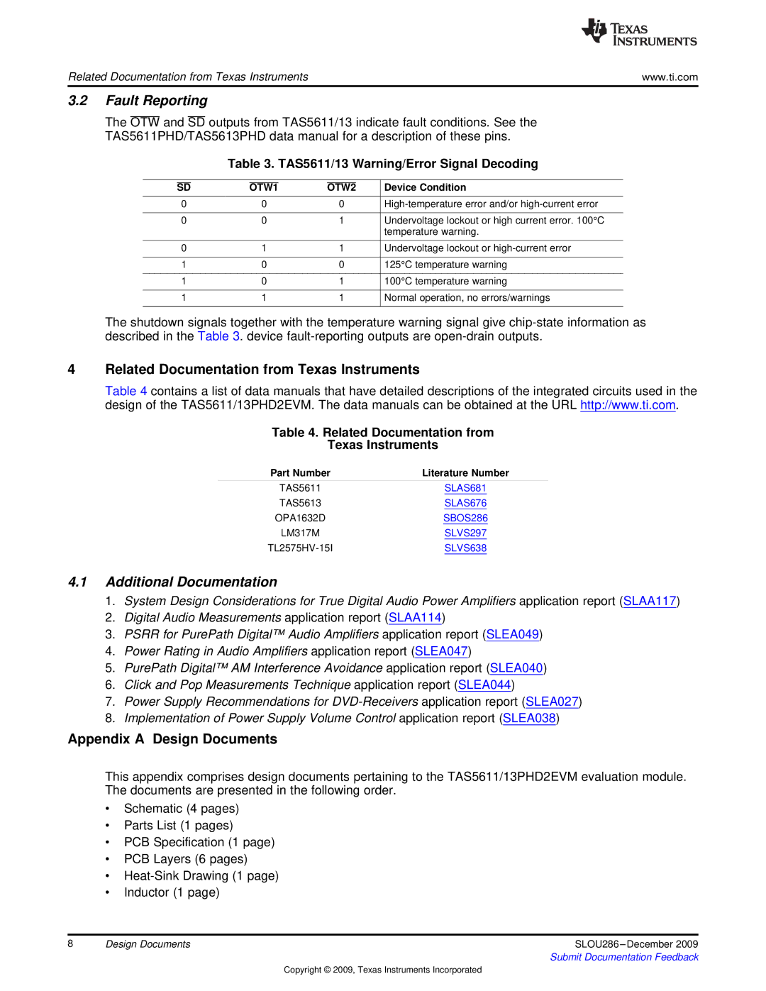
The OTW and SD outputs from TAS5611/13 indicate fault conditions. See the TAS5611PHD/TAS5613PHD data manual for a description of these pins.
Table 3. TAS5611/13 Warning/Error Signal Decoding
|
|
|
|
|
|
|
|
| SD | OTW1 | OTW2 | Device Condition | |||
0 |
| 0 |
| 0 |
| ||
|
|
|
|
|
|
|
|
0 |
| 0 |
| 1 |
| Undervoltage lockout or high current error. 100°C | |
|
|
|
|
|
|
| temperature warning. |
|
|
|
|
|
|
|
|
0 |
| 1 |
| 1 |
| Undervoltage lockout or | |
|
|
|
|
|
|
|
|
1 |
| 0 |
| 0 |
| 125°C temperature warning | |
|
|
|
|
|
|
|
|
1 |
| 0 |
| 1 |
| 100°C temperature warning | |
|
|
|
|
|
|
|
|
1 |
| 1 |
| 1 |
| Normal operation, no errors/warnings | |
|
|
|
|
|
|
|
|
The shutdown signals together with the temperature warning signal give
4Related Documentation from Texas Instruments
Table 4 contains a list of data manuals that have detailed descriptions of the integrated circuits used in the design of the TAS5611/13PHD2EVM. The data manuals can be obtained at the URL http://www.ti.com.
Table 4. Related Documentation from
Texas Instruments
Part Number | Literature Number |
TAS5611 | SLAS681 |
TAS5613 | SLAS676 |
OPA1632D | SBOS286 |
LM317M | SLVS297 |
SLVS638 |
4.1Additional Documentation
1.System Design Considerations for True Digital Audio Power Amplifiers application report (SLAA117)
2.Digital Audio Measurements application report (SLAA114)
3. PSRR for PurePath Digital™ Audio Amplifiers application report (SLEA049)
4.Power Rating in Audio Amplifiers application report (SLEA047)
5. PurePath Digital™ AM Interference Avoidance application report (SLEA040)
6.Click and Pop Measurements Technique application report (SLEA044)
7.Power Supply Recommendations for
8.Implementation of Power Supply Volume Control application report (SLEA038)
Appendix A Design Documents
This appendix comprises design documents pertaining to the TAS5611/13PHD2EVM evaluation module. The documents are presented in the following order.
•Schematic (4 pages)
•Parts List (1 pages)
•PCB Specification (1 page)
•PCB Layers (6 pages)
•
•Inductor (1 page)
8 | Design Documents | SLOU286 |
|
| Submit Documentation Feedback |
Copyright © 2009, Texas Instruments Incorporated