Manuals
/
Texas Instruments
/
Computer Equipment
/
Power Supply
Texas Instruments
bq24010/2
manual
Physical Layouts, Board Layout, 2. Assembly View
Models:
bq24010/2
1
16
18
18
Download
18 pages
52.09 Kb
11
12
13
14
15
16
17
18
Schematic
Equipment Setup
2. Assembly View
Test Procedure
PMP Portable Power
Page 16
Image 16
Page 15
Page 17
Page 16
Image 16
Page 15
Page 17
Contents
SLUU125A
PMP Portable Power
User’s Guide
January
IMPORTANT NOTICE
EVM IMPORTANT NOTICE
EVM WARNINGS AND RESTRICTIONS
Contents
3 Schematic, Physical Layouts, and Bill of Materials
Figures
Tables
Contents
Introduction
Chapter
Page
Topic
Table 1-1. Performance Specification Summary
1.2 Performance Specification Summary
1.1 Background
Test Summary
Test Summary
2.2 Test Procedure
2.1 I/O and Jumper Connections
In place of a battery, a source meter that can sink current can easily be adjusted to test each mode
2.2.2 Equipment Setup
2.2.3 Procedure
2.2.1 Equipment
Figure 2-1. Load Test Board
4 Verify that output voltage BAT+ settles between 3.2 V and 3.95
Schematic, Physical Layouts, and Bill of Materials
Schematic
Schematic, Physical Layouts, and Bill of Materials
Physical Layouts
3.1 Schematic
1 µ F
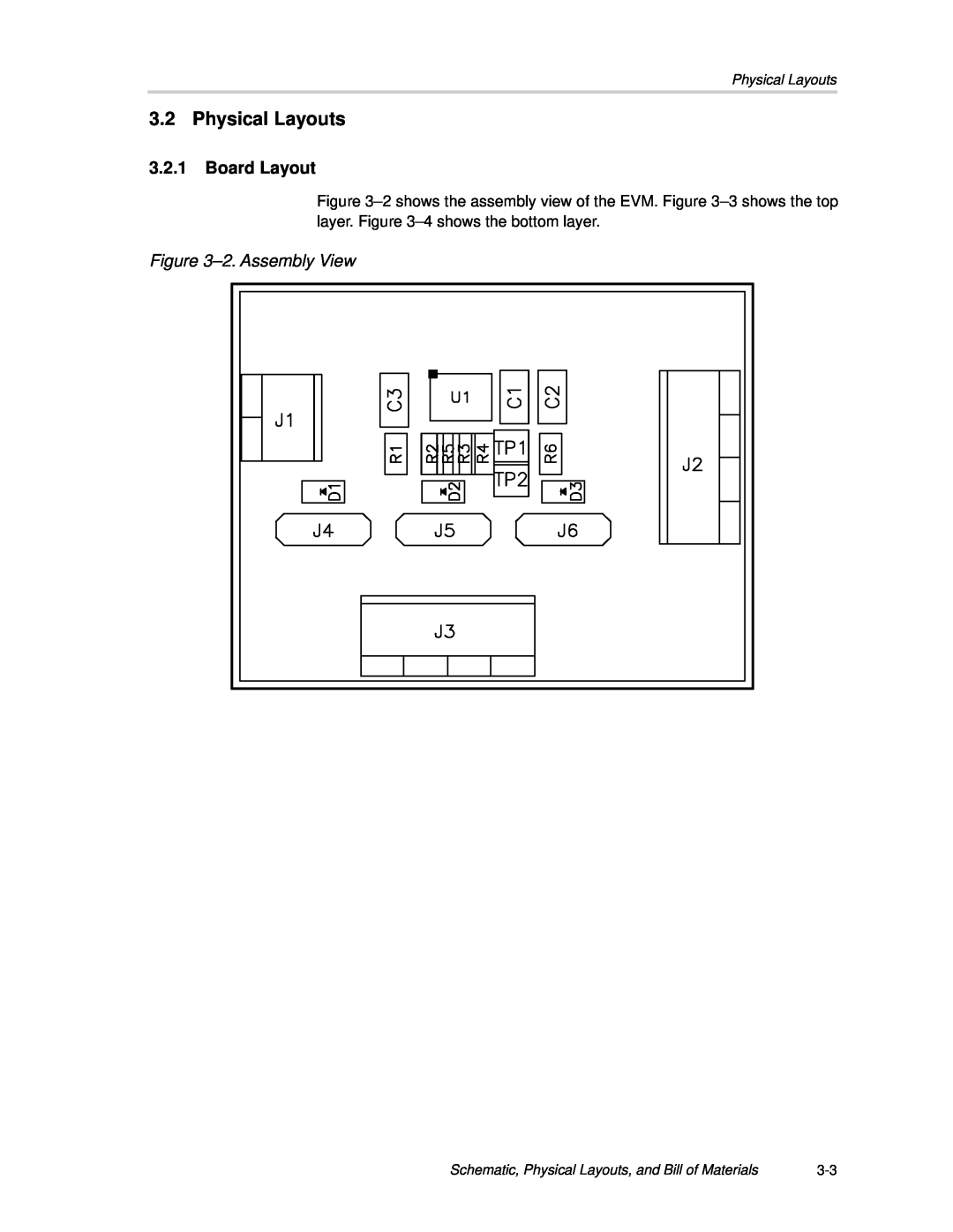
Figure 3-2. Assembly View
3.2 Physical Layouts
3.2.1 Board Layout
Physical Layouts
Figure 3-3. Top Layer Figure 3-4. Bottom Layer
3.3 Bill of Materials
3.4 Reference
Table 3-1. Bill of Materials
Bill of Materials
Top
Page
Image
Contents