Manuals
/
Texas Instruments
/
Computer Equipment
/
Network Card
Texas Instruments
DAC7741EVM
manual
Layer 3 Power Plane
Models:
DAC7741EVM
1
16
28
28
Download
28 pages
51.52 Kb
13
14
15
16
17
18
19
20
Parts list
EVM Block Diagram
Factory Default Setting
Jumper Setting
Power Requirements
Page 16
Image 16
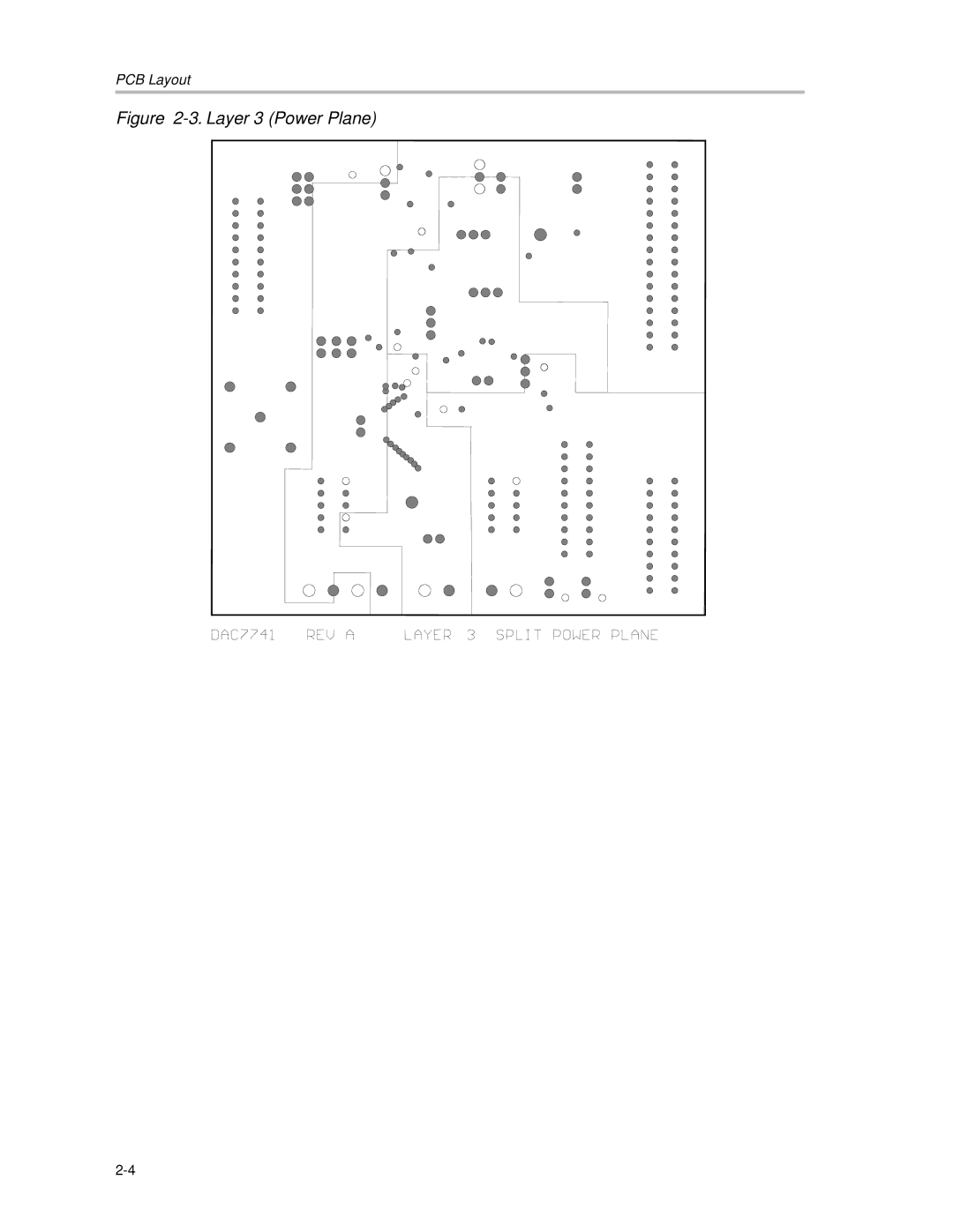
PCB Layout
Figure
2-3.
Layer 3 (Power Plane)
2-4
Page 15
Page 17
Page 16
Image 16
Page 15
Page 17
Contents
User’s Guide
Important Notice
EVM Important Notice
EVM Warnings and Restrictions
Read This First
About This Manual
Related Documentation From Texas Instruments
Contents
Figures
Tables
Features Power Requirements EVM Basic Functions
EVM Overview
Features
Power Requirements
EVM Basic Functions
EVM Block Diagram
Physical Description
PCB Layout Bill of Materials
PCB Layout
Layer One Top Silkscreen
Layer Two Ground Plane
Layer 3 Power Plane
Layer 4 Bottom Plane
Drill Drawing
Parts List
Bill of Materials
This page has been left blank intentionally
EVM Operation
Factory Default Jumper Setting
Factory Default Setting
Reference Jumper Function Position
Unity Gain Output Jumper Settings
Host Processor Operation
Reference
Unipolar Bipolar
Capacitive Load Drive Output Jumper Settings
Gain of Two Output Jumper Settings
Reference Jumper Setting Function
Jumper Setting Function
Jumper Setting
Reference Jumper Function
Jumper Function Setting
Schematic
Schematic of the DAC7741 is found on the following
DAC7741
Top
Page
Image
Contents