Factory Default Setting
3.1 Factory Default Setting
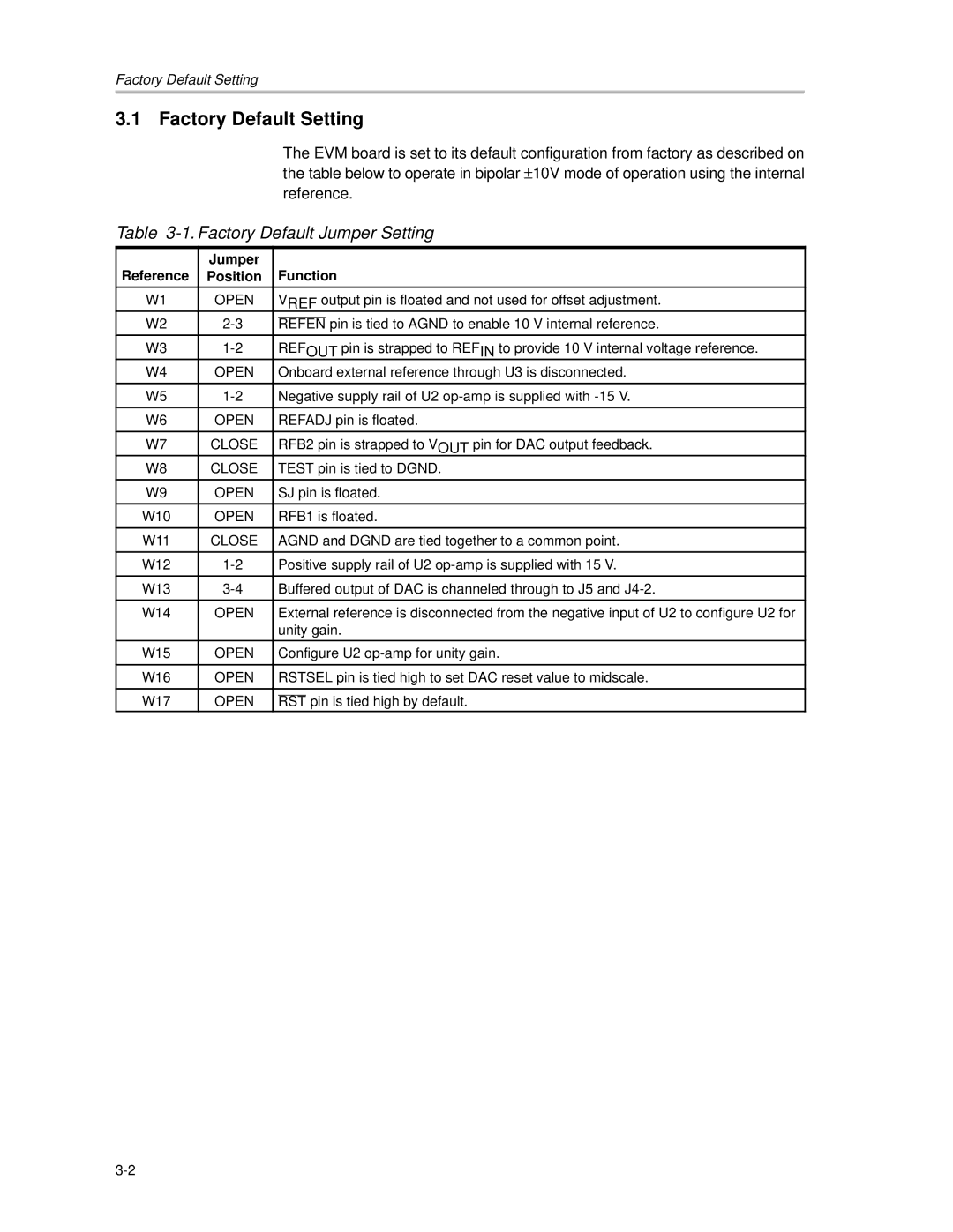
The EVM board is set to its default configuration from factory as described on the table below to operate in bipolar ±10V mode of operation using the internal reference.
Table 3-1. Factory Default Jumper Setting
Reference | Jumper |
| Function | ||
Position |
| ||||
|
|
|
|
|
|
W1 | OPEN |
| VREF output pin is floated and not used for offset adjustment. | ||
W2 |
|
|
| pin is tied to AGND to enable 10 V internal reference. | |
REFEN | |||||
W3 |
| REFOUT pin is strapped to REFIN to provide 10 V internal voltage reference. | |||
W4 | OPEN |
| Onboard external reference through U3 is disconnected. | ||
|
|
|
|
| |
W5 |
| Negative supply rail of U2 | |||
|
|
|
|
| |
W6 | OPEN |
| REFADJ pin is floated. | ||
|
|
|
|
| |
W7 | CLOSE |
| RFB2 pin is strapped to VOUT pin for DAC output feedback. | ||
W8 | CLOSE |
| TEST pin is tied to DGND. | ||
|
|
|
|
| |
W9 | OPEN |
| SJ pin is floated. | ||
|
|
|
|
| |
W10 | OPEN |
| RFB1 is floated. | ||
|
|
|
|
| |
W11 | CLOSE |
| AGND and DGND are tied together to a common point. | ||
|
|
|
|
| |
W12 |
| Positive supply rail of U2 | |||
|
|
|
|
| |
W13 |
| Buffered output of DAC is channeled through to J5 and | |||
|
|
|
|
| |
W14 | OPEN |
| External reference is disconnected from the negative input of U2 to configure U2 for | ||
|
|
| unity gain. | ||
W15 | OPEN |
| Configure U2 | ||
|
|
|
|
| |
W16 | OPEN |
| RSTSEL pin is tied high to set DAC reset value to midscale. | ||
|
|
|
|
| |
W17 | OPEN |
|
| pin is tied high by default. | |
| RST | ||||