DEM-DAI1717 SYSTEM BOARD INFORMATION
GENERAL SPECIFICATIONS
Table I lists the specifications for the
SPDIF Interface | Optical via Toslink |
| RCA with 75Ω impedance. |
|
|
System Clock Frequency | 256 times sampling frequency, fs |
|
|
Digital Audio Interface | 16 bits, Normal Format, MSB last |
| 18 bits, Normal Format, MSB last |
| I2S 16 or 18 bits |
THD+N | 0.004% typical, with internal 20kHz Low |
| Pass Filter. |
| 0.08% typical, direct out, with external |
| 30kHz Low Pass Filter. |
|
|
Dynamic Range | 94dB typical, (EIAJ method, |
| filter) |
|
|
SNR | 100dB typical, (EIAJ method, |
| filter) |
|
|
Maximum Output | 2Vrms (using internal low pass filter out) |
|
|
+VCC range | +4.5 to +5.5 |
+ICC | +60mA (no external load) to +120mA |
±VS | ±5V ~ ±15V |
±IS | ±15mA (no external load) |
|
|
TABLE I.
SPDIF INTERFACE OPTIONS
The
|
|
| S0 |
|
| S1 |
| S2 |
| ||
|
| L |
|
|
|
|
|
|
|
|
|
|
|
|
|
|
|
|
|
|
|
| |
|
| H |
|
|
|
|
|
|
|
|
|
|
|
|
|
|
|
|
| ||||
| S0 | S1 | S2 |
|
| SPDIF Output Format |
| ||||
| H | L | H |
| 16 bits Normal Format MSB First |
| |||||
| L | H | H |
| 18 bits Normal Format MSB First |
| |||||
| L | H | L |
|
|
| I2S 16 or 18 bits |
| |||
|
|
|
|
|
|
|
|
|
|
|
|
FIGURE 7. SPDIF Interface Options.
JUMPER SETTINGS
The
![]()
![]()
![]()
![]()
![]()
![]()
![]()
![]()
![]() ®
®
installed by default. An optional ground connection can be made between the receiver chip and the PCM1717E. Refer to Figure 8 for the orientation of these jumpers.
JP
256fs
LRCK
BCK
DATA
GND
CS8412 PCM1717E
FIGURE 8. DEM-DAI1717 Jumper Configuration.
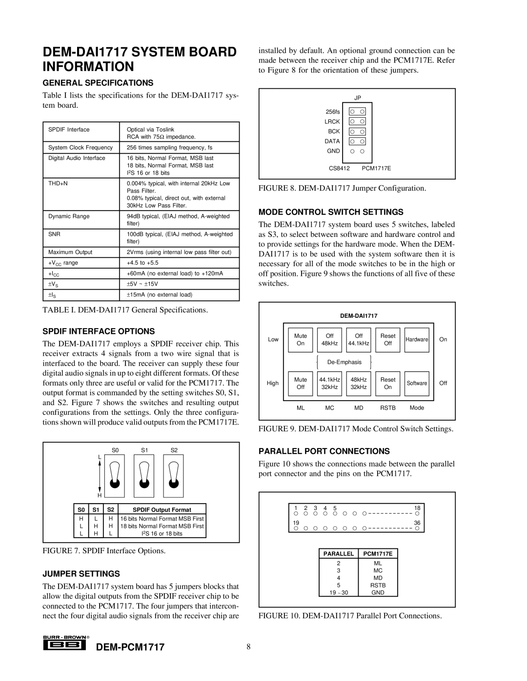
MODE CONTROL SWITCH SETTINGS
The
|
|
|
|
|
|
|
|
|
| |||||
|
|
|
|
|
|
|
|
|
|
|
|
|
|
|
|
|
|
|
|
|
|
|
|
|
|
|
|
|
|
Low |
| Mute |
| Off |
|
| Off |
|
| Reset |
| Hardware |
| On |
| On |
| 48kHz |
|
| 44.1kHz |
|
| Off |
|
| |||
|
|
|
|
|
|
|
|
|
|
| ||||
|
|
|
|
|
|
|
|
|
|
|
|
|
| |
|
|
|
|
|
|
|
|
| ||||||
|
|
|
|
|
|
|
|
|
|
|
|
|
|
|
High |
| Mute |
| 44.1kHz |
|
| 48kHz |
|
| Reset |
| Software |
| Off |
| Off |
| 32kHz |
|
| 32kHz |
|
| On |
|
| |||
|
|
|
|
|
|
|
|
|
|
| ||||
|
|
|
|
|
|
|
|
|
|
|
|
|
|
|
|
|
|
|
|
|
|
|
|
|
|
|
| ||
|
| ML |
| MC |
|
| MD | RSTB |
| Mode |
|
| ||
FIGURE 9. DEM-DAI1717 Mode Control Switch Settings.
PARALLEL PORT CONNECTIONS
Figure 10 shows the connections made between the parallel port connector and the pins on the PCM1717.
1 | 2 | 3 | 4 | 5 | 18 |
19 |
|
|
|
| 36 |
|
|
| PARALLEL | PCM1717E | |
|
|
|
| 2 | ML |
|
|
|
| 3 | MC |
|
|
|
| 4 | MD |
|
|
|
| 5 | RSTB |
|
|
|
| 19 ~ 30 | GND |