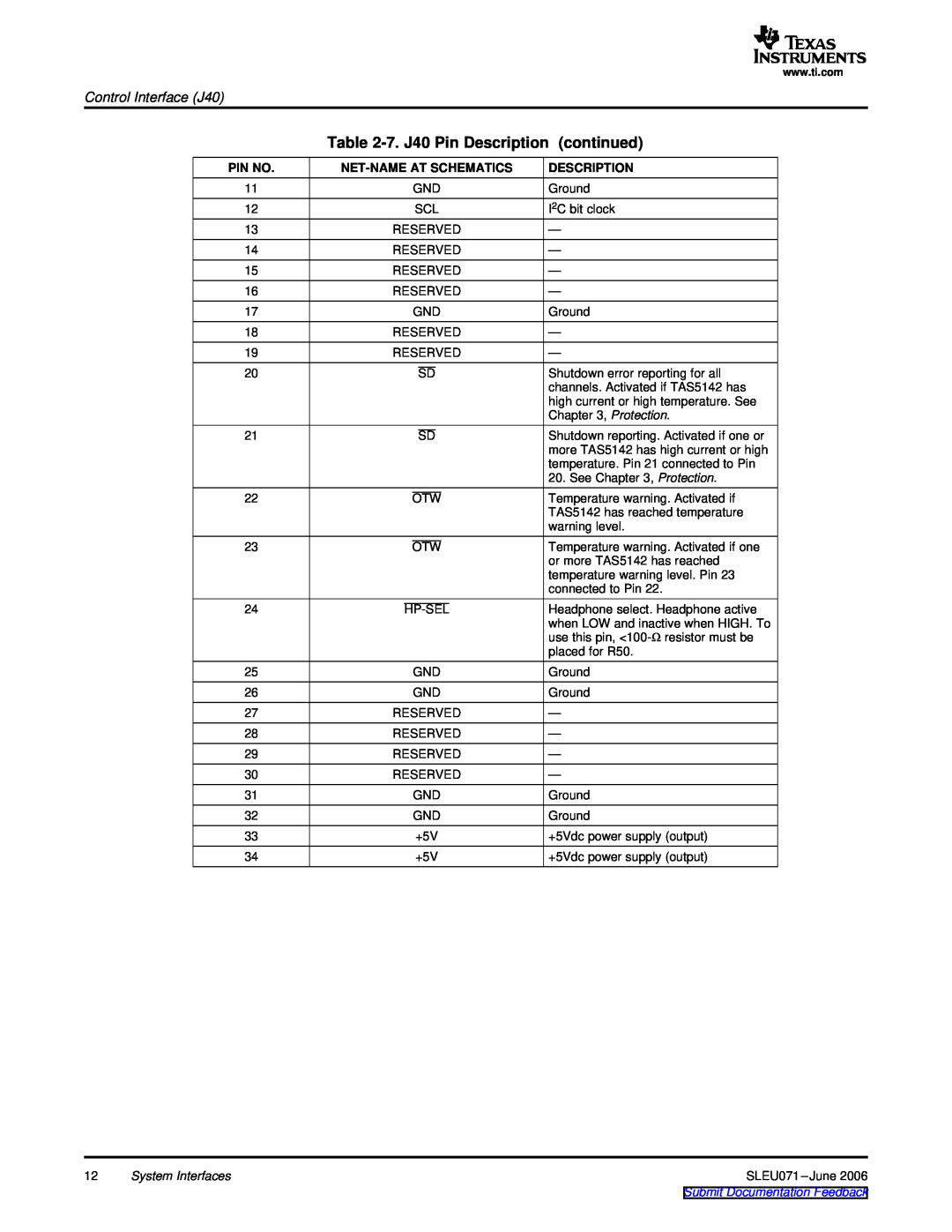
The Control Interface J40 provides essential information about the pin numbers, net names, and descriptions for Texas Instruments TAS5508-5142K7EVM Stereo Amplifier.
How many pins does the Control Interface J40 have?
The Control Interface J40 consists of 24 pins, each serving a specific function in the amplifier's control interface.
Where can I find more information about the pin functions of the TAS5508-5142K7EVM?
You can refer to the official manual for the Texas Instruments TAS5508-5142K7EVM for detailed information about the pin functions and control interface.
Are there any recommended accessories for using the Control Interface J40 effectively?
To use the Control Interface J40 effectively, it is recommended to follow the guidelines provided in the official manual for the TAS5508-5142K7EVM and consult with technical experts if necessary.
What precautions should I take while working with the Control Interface J40?
When working with the Control Interface J40, it is important to follow the safety guidelines provided in the official manual and ensure proper handling of the amplifier.
How to connect the Reserved pins in the Control Interface J40?
The official manual for the Texas Instruments TAS5508-5142K7EVM provides detailed instructions on how to connect and utilize the reserved pins in the Control Interface J40.
What are the key features of the TAS5508-5142K7EVM Stereo Amplifier?
The TAS5508-5142K7EVM Stereo Amplifier offers a range of advanced features, including a comprehensive control interface with detailed pin descriptions in the J40 interface.
Why is the Control Interface J40 important for the TAS5508-5142K7EVM?
The Control Interface J40 plays a crucial role in enabling precise control and management of the TAS5508-5142K7EVM Stereo Amplifier, ensuring optimal performance and functionality.
How to troubleshoot issues related to the Control Interface J40?
In case of any issues with the Control Interface J40, it is recommended to refer to the troubleshooting section of the official manual and seek technical support if needed.
Where can I find the pin assignments for the TAS5508-5142K7EVM's Control Interface J40?
The pin assignments for the Control Interface J40 of the TAS5508-5142K7EVM can be found in the official manual, providing detailed information for each pin's functionality.