Texas Instruments TAS5508-5142K7EVM manual 1.2PCB Key Map, Overview, Submit Documentation Feedback

Models: TAS5508-5142K7EVM

1 20
Download 20 pages 18.51 Kb
Page 7
Image 7
PCB Key Map

www.ti.com

PCB Key Map

1.2PCB Key Map

Physical structure for the TAS5508-5142K7EVM is illustrated in Figure 1-2.

PSU


PSU


CONTROL


J107

J106

J105


J104

J102

J103

J101


INTERFACE


(J902)


(J900)


SPEAKER￿OUTPUTS


SPEAKER￿OUTPUTS


OUTPUT STAGE

CHANNEL 7

OUTPUT STAGE

CHANNEL 6

OUTPUT STAGE

CHANNEL 5

OUTPUT STAGE

CHANNEL 4

OUTPUT STAGE

CHANNEL 2

OUTPUT STAGE

CHANNEL 3

OUTPUT STAGE

CHANNEL 1

PSU INTERFACE (J901)

Gate Drive Regulator


TAS5508B


5V Regulator


HEADPHONE


OUTPUT


3.3V


(J700)


Regulator


CONTROL


INPUT SIGNAL


INTERFACE (J40)


INTERFACE (J60)


Figure 1-2. Physical Structure for TAS5508-5142K7EVM (Rough Outline)

SLEU071 –June 2006

Overview

7

Submit Documentation Feedback

Page 7
Image 7
Texas Instruments TAS5508-5142K7EVM manual 1.2PCB Key Map, Overview, Submit Documentation Feedback

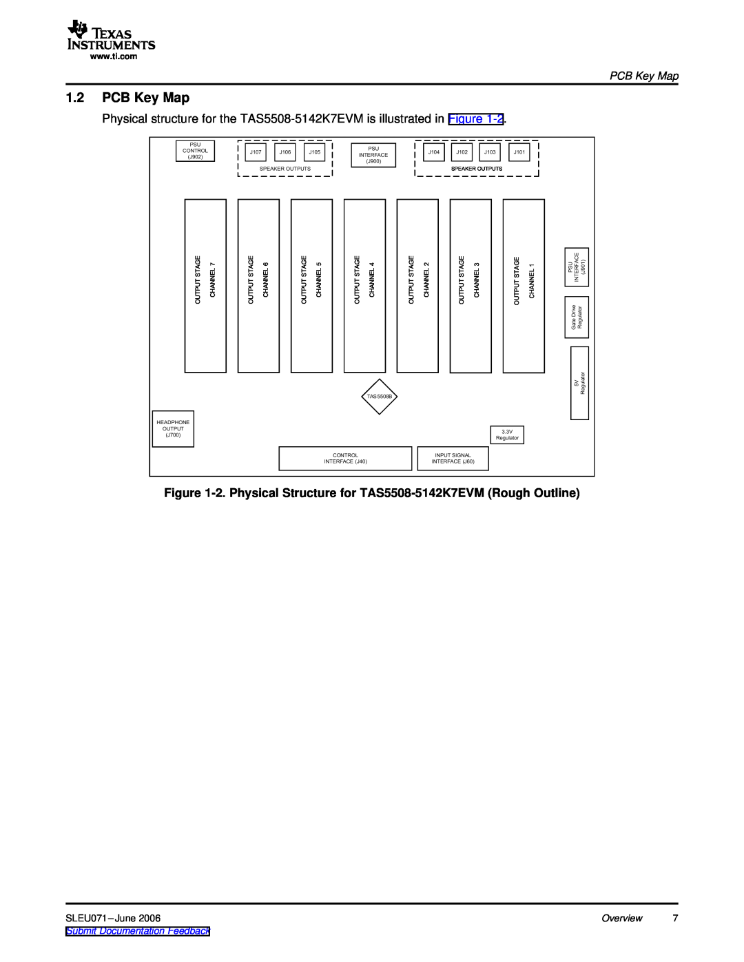
FAQ

What is the physical structure of the TAS5508-5142K7EVM?

The physical structure for the TAS5508-5142K7EVM is illustrated in the PCB Key Map.

Where can I find a schematic diagram for the TAS5508-5142K7EVM?

You can find the schematic diagram in the official manual for this amplifier model.

How do I give feedback on the documentation?

You can submit documentation feedback at the end of the official manual page.