Description
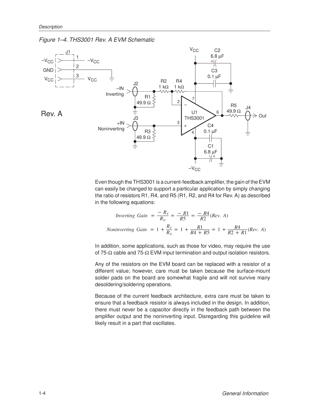
Figure 1±4. THS3001 Rev. A EVM Schematic
| J1 |
|
|
|
| VCC | C2 |
|
|
|
|
|
|
| 6.8 μF |
| |
±VCC | 1 | ±VCC |
|
|
|
|
| |
2 |
|
|
|
| + |
| ||
GND |
|
|
|
|
| C3 |
| |
3 |
|
|
|
|
|
| ||
VCC | VCC |
| R2 | R4 |
| 0.1 μF |
| |
| J2 |
|
|
| ||||
|
| ±IN | 1 kΩ | 1 kΩ |
|
|
| |
|
|
|
|
|
| |||
|
|
|
|
|
|
|
| |
|
| Inverting | R1 |
|
| 7 |
|
|
|
|
|
| 2 |
|
| ||
|
|
| 49.9 Ω |
|
|
| ||
|
|
|
| ± | R5 | J4 | ||
|
|
|
|
|
| |||
Rev. A |
|
|
|
|
| U1 | 6 49.9 Ω | |
|
|
|
|
| Out | |||
|
| J3 |
|
| THS3001 | |||
|
| +IN |
| 3 |
| |||
|
|
|
| + | C4 |
| ||
|
| Noninverting |
|
|
|
| ||
|
| R3 |
|
| 4 | 0.1 μF |
| |
|
|
|
|
|
| |||
|
|
| 49.9 Ω |
|
|
|
|
|
|
|
|
|
|
|
| C1 |
|
|
|
|
|
|
|
| 6.8 μF |
|
|
|
|
|
|
|
| + |
|
|
|
|
|
|
| ±VCC |
|
|
Even though the THS3001 is a
Inverting Gain + | *RF +*R1 +*R4 | (Rev. A) |
| |||||||||
RG |
|
| R5 | R2 |
| |||||||
|
|
|
|
|
|
|
| |||||
Noninverting Gain +1 ) | RF | +1 ) | R1 |
| +1 ) |
| R4 |
| (Rev. A) | |||
RG | R4 )R5 | R2 )R1 | ||||||||||
|
|
|
|
| ||||||||
In addition, some applications, such as those for video, may require the use of
Any of the resistors on the EVM board can be replaced with a resistor of a different value; however, care must be taken because the
Because of the current feedback architecture, extra care must be taken to ensure that a feedback resistor is always included in the design. In addition, there must never be a capacitor directly in the feedback path between the amplifier output and the noninverting input. Disregarding this guideline will likely result in a part that oscillates.
General Information |