Description
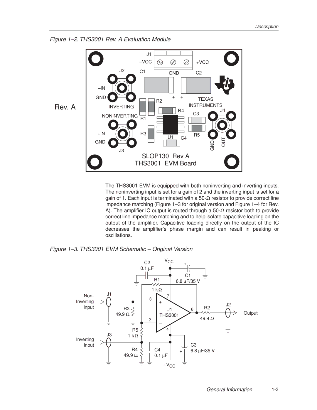
Figure 1±2. THS3001 Rev. A Evaluation Module
| J1 |
|
|
| ±VCC |
| +VCC |
J2 | C1 | GND | C2 |
|
|
Rev. A
±IN
GND ![]()
![]() INVERTING
INVERTING
NONINVERTING
+IN
GND
J3
![]()
![]() R2
R2
R1
R3 ![]()
![]()
+ | + | TEXAS |
|
| |
|
| INSTRUMENTS |
| R4 | J4 |
|
| C3 |
U1 | R5 |
|
C4 | OUT | |
| GND |
SLOP130 Rev A
THS3001 EVM Board
The THS3001 EVM is equipped with both noninverting and inverting inputs. The noninverting input is set for a gain of 2 and the inverting input is set for a gain of 1. Each input is terminated with a
Figure 1±3. THS3001 EVM Schematic ± Original Version
|
| C2 | VCC |
| + |
|
|
| 0.1 μF |
|
|
| |
|
|
| R1 |
| C1 |
|
|
|
| 6.8 μF/35 V |
| ||
| J1 |
| 1 k Ω |
|
|
|
Non- | 3 | 7 |
|
|
| |
|
|
|
| |||
Inverting |
| + |
|
|
| |
|
|
|
| J2 | ||
Input |
|
|
|
|
| |
| R3 | U1 |
| 6 | R2 | |
|
| 49.9 Ω | THS3001 |
| Output | |
|
| 2 | ± |
|
| 49.9 Ω |
|
|
|
|
| ||
|
|
|
|
|
| |
| J3 | R5 | 4 |
|
|
|
Inverting | 1 k Ω |
|
|
|
| |
|
|
|
|
|
| |
Input |
| R4 | C4 |
| C3 |
|
|
| + | 6.8 μF/35 V | |||
|
| 49.9 Ω | 0.1 μF |
|
|
|
±VCC
General Information |